
Metal microparticles provided with projections

a technology of metal microparticles and projections, which is applied in the field of metal microparticles, can solve the problems of low resistance value, delamination, and insufficient study of the ratio (d/d) of a crystallite diameter (d) to a particle diameter (d) size, so as to improve catalytic properties, reduce thermal shrinkage and deterioration, and enhance the electric conductivity characteristics

Active Publication Date: 2015-10-29
M TECHN
View PDF1 Cites 0 Cited by
  • Summary
  • Abstract
  • Description
  • Claims
  • Application Information

AI Technical Summary

Benefits of technology

The present invention provides a new metal microparticle that has improved electric conductivity and catalytic properties. The metal microparticle has a particle body with a projection that sticks out from it. The projection can deform at a lower temperature than the main body of the metal, allowing the particles to fuse together and create a network of electrically conductive particles. This results in a lower energy requirement for creating an electrically conductive microparticle and a wiring member, and it also prevents agglomeration of the metal microparticles. Overall, this metal microparticle has improved properties and can be used in various applications.

Problems solved by technology

If this microparticle is laminated with the same material or composed of a different material, there are problems of delamination and of characteristic change because physical properties such as thermal expansion are different therebetween.
The nickel microparticle such as the one described in Patent Document 3, which has particle diameter of 0.1 to 10 μm and on outer surface thereof a number of projections whose heights are less than ¼ relative to the particle diameter, has been disclosed; however, in this microparticle, it is difficult to keep sufficient contact because of the small projections; and therefore, it has been difficult to realize to prevent the poor conductivity, to lower the resistance value, etc.
Moreover, in any of these Documents, the study on the ratio (d / D) of a crystallite diameter (d) to a particle diameter (D) has not been carried out extensively.
However, actually, the investigation with regard to this point has not been carried out extensively.

Method used


Image

  • Metal microparticles provided with projections
  • Metal microparticles provided with projections
  • Metal microparticles provided with projections

Examples


Embodiment Construction

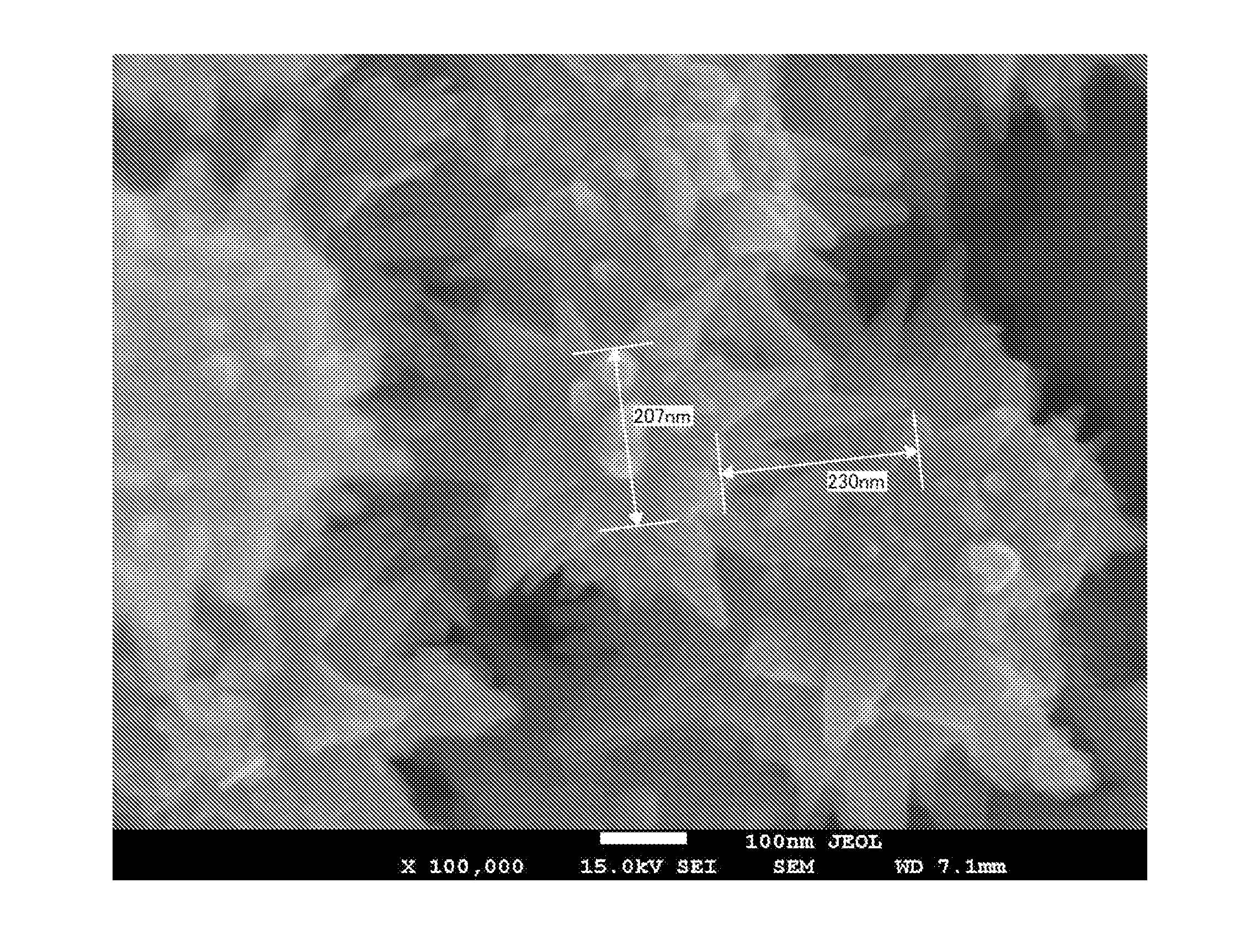
[0042]The metal microparticle of the present invention is the metal microparticle having a projection. It is preferable that this projection be integrated with the main body thereof; and the embodiment thereof may be singular or plural. As can be seen in FIG. 23(A), the height (H) of at least one projection is preferably more than ¼ relative to the particle diameter (D) of the particle main body. The projection is preferably in a conical shape such as a polygonal cone and a circular cone. Shape of the projection may be all in the same or different. In addition, the metal microparticle of the present invention is the fine microparticle having the size of 5 μm or less, or preferably 1 μm or less.

[0043]More specifically, the particle diameter (D) thereof is preferably in the range of 10 to 1000 nm, more preferably in the range of 20 to 1000 nm, or still more preferably in the range of 50 to 1000 nm. If the particle diameter (D) is less than 10 nm, the possibility may be presumed that d...


PUM

PropertyMeasurementUnit
particle diameteraaaaaaaaaa
heightaaaaaaaaaa
particle diameteraaaaaaaaaa

Abstract

In response to the demand for shape-controlled metal microparticles accompanying rapid development and progress in industry in recent years, metal microparticles, which have projections on the surfaces of the particles that are integrated with the particles, are provided. The metal microparticles have integrated conical projections on the surfaces of the particles, and at least some of the projections are more than ¼ of the size of the particles. The protrusions that protrude from the metal microparticles melt and deform at a temperature lower than the melting point of the metal itself.

Description

TECHNICAL FIELD[0001]The present invention relates to metal microparticle including a nickel element contained therein and being provided with a projection having a shape apparently tapering-off to a point, such as a conical projection.BACKGROUND ART[0002]Nickel microparticle is used in such applications as an electrically conductive material and a catalyst; and it is the material drawing a keen attention in recent years. Metal microparticle such as nickel microparticle is different in its required characteristics depending on the filed in which it is used; and thus, it is considered to be necessary to control the shape of the particle in addition to control of particle diameter and crystallite diameter thereof. For example, in the electrically conductive microparticle used for electrical connection of a circuit substrate etc., in order to increase the contacting sites in the matrix as well as to enhance the electric conductivity performance, particles having projections on surface ...

Claims


Application Information

Patent Timeline
Patent Type & Authority Applications(United States)
IPC IPC(8): H01B1/02B01J23/755B01J35/02B22F9/24B22F1/00B22F1/065
CPCH01B1/02B01J35/026B01J23/755B22F9/24B22F1/065B22F1/00B01J35/50B22F9/00
Inventor MAEKAWA, MASAKIENOMURA, MASAKAZU
Owner M TECHN
Learn More