Electronic arrangement comprising a circuit board

a circuit board and circuit board technology, applied in the field of electronic arrangement, can solve the problems of affecting the operation of the circuit board, so as to improve the installation space, reliable tolerance compensation, and improve the effect of installation spa

Active Publication Date: 2015-10-29
ROBERT BOSCH GMBH
View PDF24 Cites 9 Cited by
  • Summary
  • Abstract
  • Description
  • Claims
  • Application Information

AI Technical Summary

Benefits of technology

[0003]In contrast thereto, the electronic arrangement in accordance with the invention comprises the advantage that it is possible to achieve a reliable tolerance compensation in the case of a directly contactable circuit board. This has a particular advantage that the solution in accordance with the invention does not require increased installation space. Nevertheless, it is possible to compensate reliably for tolerances between different circuit board thicknesses. This is achieved in accordance with the invention by virtue of the fact that the circuit board that comprises one electrical contact surface for a direct contact is arranged in a housing having a plug collar and the circuit board can be supported on a first circuit board half by means of a mounting. The mounting for the purpose of supporting the circuit board is embodied in such a manner that the mounting defines a circuit board pivot region about which the circuit board can pivot. Consequently, the circuit board is arranged in a pivotable manner in the housing and can thus reliably compensate for different circuit board thicknesses. The mounting for the circuit board is preferably provided in a region of the circuit board, said region being remote from the plug collar, in order for the circuit board to be able to move sufficiently with as far as possible only one minimal pivot angle. The pivot angle is preferably in a range of +10° about a horizontal plane, particularly preferred in a range of +5°. Consequently, in accordance with the invention, the circuit board is only finally fixed in place after a plug has been inserted into the plug collar.

Problems solved by technology

However, this arrangement is encumbered with problems relating to contamination in the contact region or rather relating to dirt entering the interior of the control device.
One problematic area of direct plug connections of this type resides in the fact that the circuit boards are frequently of different thicknesses.
These comparatively large tolerances of a thickness of a circuit board cause an asymmetric arrangement of the circuit board relative to a plug collar and possibly cause force to be exerted in an asymmetric manner when making the contact.
However, due to the fact that many users desire arrangements that have small dimensions, this leads to problems when making the contacts and even to the circuit board and / or the plug being damaged during the mounting process.

Method used


Image

  • Electronic arrangement comprising a circuit board
  • Electronic arrangement comprising a circuit board
  • Electronic arrangement comprising a circuit board

Examples


Embodiment Construction

[0021]An electronic arrangement 1 in accordance with a first preferred exemplary embodiment of the invention is described in detail hereinunder with reference to the FIGS. 1 to 6.

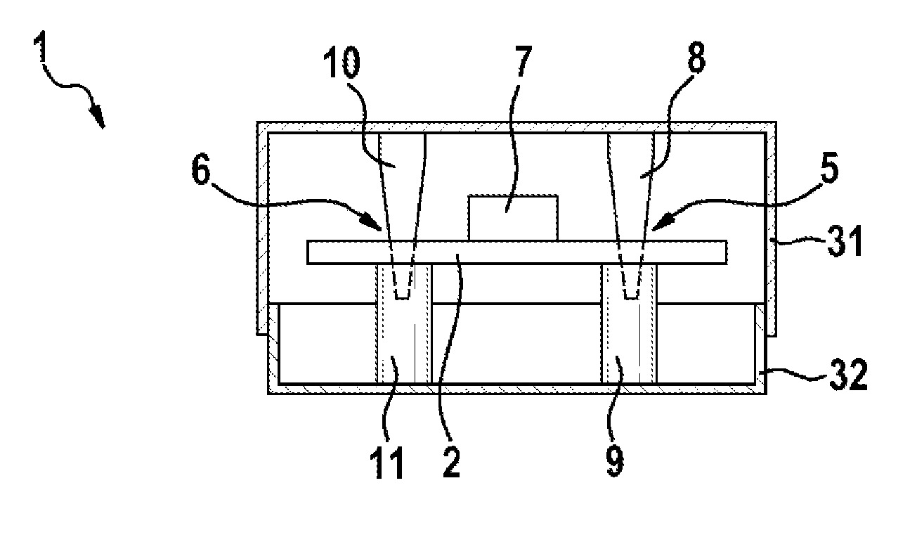
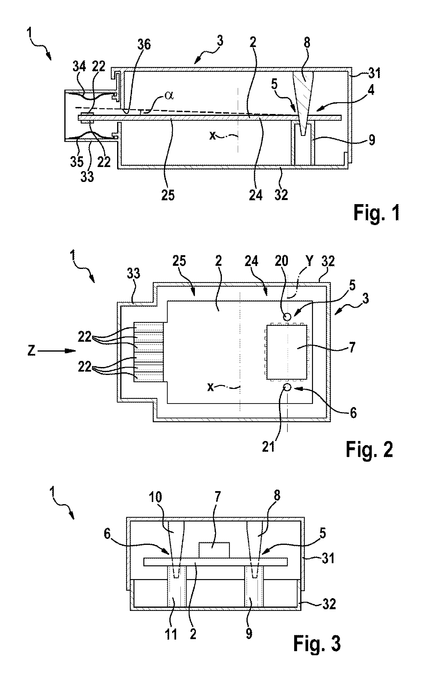
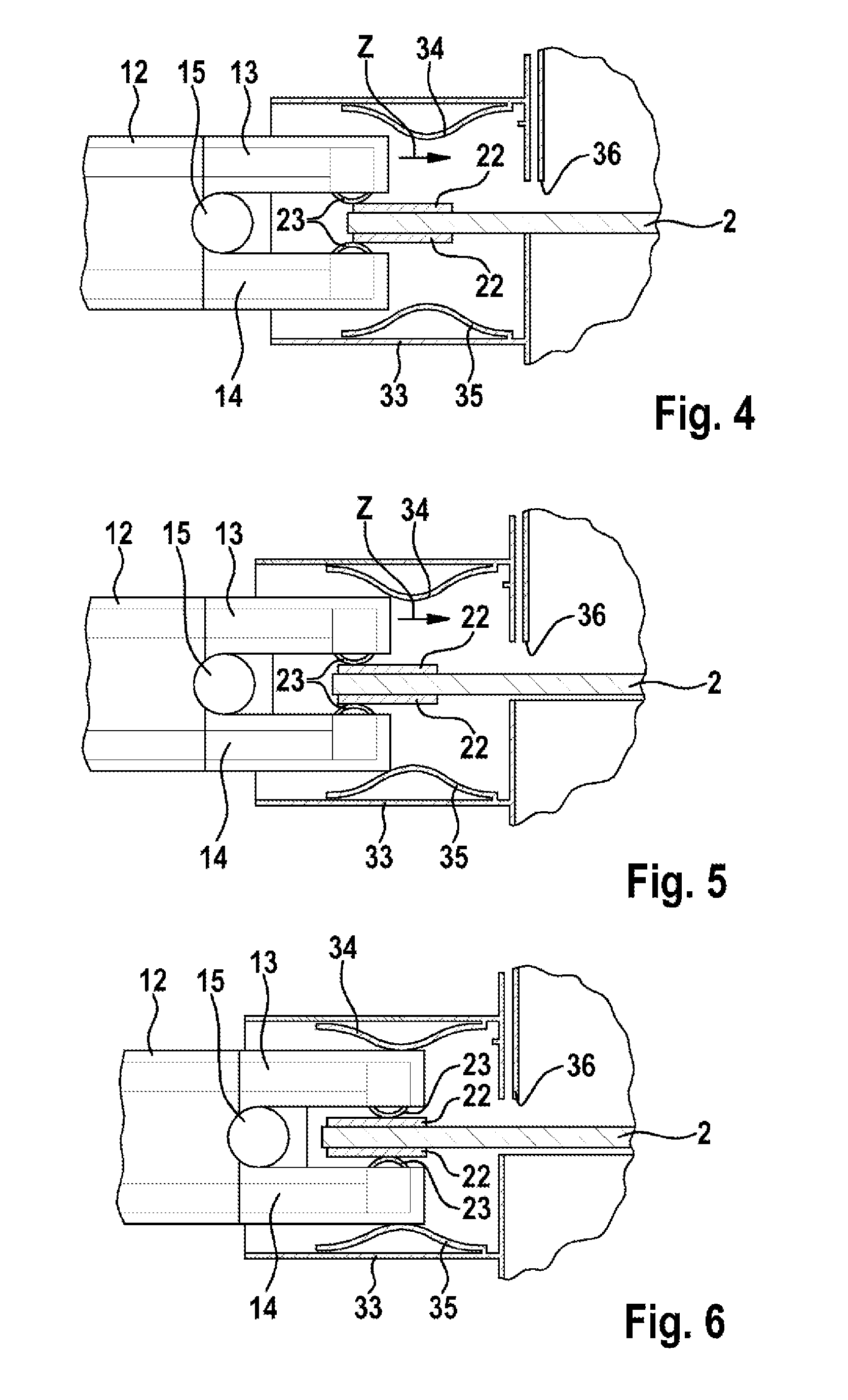
[0022]As is evident in FIG. 1, the electronic arrangement comprises a circuit board 2 that is arranged in a housing 3. The housing 3 is embodied in two parts having a first part 31 and a second part 32. Moreover, the housing 3 comprises a plug collar 33 for the purpose of receiving a plug 12 (cf. FIGS. 4 to 6).

[0023]The electronic arrangement 1 comprises moreover a mounting 4 for the purpose of supporting the circuit board 2. As is evident in FIGS. 2 and 3, the mounting 4 comprises a first mounting region 5 and a second mounting region 6. The two mounting regions 5, 6 each form an essentially spot-like mounting for the circuit board 2 so that a straight line Y through the two mounting regions 5, 6 defines a pivot axis for the circuit board 2. As is evident in FIG. 1, the circuit board 2 is only supported in...


PUM


Abstract

The invention relates to an electronic arrangement having a directly contactable circuit board (2), said electronic arrangement comprising: a circuit board (2) that includes at least one electric contact for electric contacting, a housing (3) inside which the circuit board (2) is arranged, and a plug shroud (33) that is arranged on the housing (3). The circuit board (2) includes a first circuit board half (24) that has a support (4) for supporting the circuit board (4), and a second circuit board half (25). The circuit board (2) is supported on the support (4) in such a way that the support (4) defines a swivel region, in particular a swivel axis of the circuit board (2), about which the circuit board (2) can swivel.

Description

BACKGROUND OF THE INVENTION[0001]The prevent invention relates to an electronic arrangement having a directly contactable circuit board, wherein a plug produces a direct electric contact on the circuit board.[0002]It is known to produce a so-called direct plug connection between a circuit board and a plug, wherein the electric contacts of the plug are plugged directly onto contact surfaces on the circuit board. The circuit board can be part of a control device or also part of an electric assembly, for example an electric drive. However, this arrangement is encumbered with problems relating to contamination in the contact region or rather relating to dirt entering the interior of the control device. Furthermore, requirements with regard to anti-contact protection are to be fulfilled in the contact region. An electric window lever drive is known by way of example from DE 10201002511 A1, wherein a direct plug connection of this type is achieved. One problematic area of direct plug conn...

Claims


Application Information

Patent Timeline
Patent Type & Authority Applications(United States)
IPC IPC(8): H05K7/14
CPCH05K7/1417H05K1/117H05K5/006H05K5/0069H05K2201/09754H05K2201/09063
Inventor KROECKEL, MARKUSGUECKEL, RICHARD
Owner ROBERT BOSCH GMBH
Why Eureka
Try Eureka