Optical amplifier and gain tilt compensation method

a technology of optical amplifier and gain tilt compensation, which is applied in the field of optical amplifier, can solve the problems of limited output power, impaired amplification efficiency, and difficult downsizing, and achieve the effects of reducing increasing the length of erbium-doped fiber, and improving the amplification efficiency of optical amplifier

Inactive Publication Date: 2006-07-04
FUJITSU LTD
View PDF15 Cites 7 Cited by
  • Summary
  • Abstract
  • Description
  • Claims
  • Application Information

AI Technical Summary

Benefits of technology

[0022]Another object of the invention is to reduce the length of EDFs used in the EDFAs which amplify optical signals at wavelengths of 1570 to 1650 nm (the L-band and the L+-band), so that various problems due to the increased length of EDFs can be solved.
[0039]The gain tilt compensation method of the present invention is advantageous in that tilts, if any, in gain obtained by the foregoing optical amplifier can be reliably compensated for.

Problems solved by technology

Such a Raman amplifier is advantageous in that it can amplify optical signals at arbitrary wavelengths by selecting the wavelength of a pump beam, whereas it has a disadvantage of limited output power caused by nonlinear effects such as four-wave mixing.
Additionally, when the Raman amplifier amplifies optical signals in the S-band, the wavelength of the pump beam falls in a range in which optical fibers exhibit greater loss, so that the amplification efficiency is impaired.
Moreover, since gain per unit length is small, the Raman amplifier requires several to several tens of kilometers of fiber (optical amplifier medium) for optical amplification, making downsizing difficult.
The TDFA, however, has a disadvantage of reduced yield because of the use of a fluoride-based fiber, and its reliability is still rather poor.
Even with such anew optical amplifier, it is still difficult to amplify optical signals at wavelengths of 1510 to 1530 nm, out of a band ranging from 1490 to 1530 nm {the S-band (the shorter-wavelength band)}.
Amplified spontaneous emission (ASE) in the C-band thus significantly grows, thereby impairing the efficiency of amplification in the S-band and the S+-band.
Further, even if this optimization achieves amplification of optical signals in the S-band and the S+-band, it is still necessary to compensate with certainty for gain tilts caused by manufacturing errors of the optical filters or others.
Only when there are such multiple EDFs and multiple optical filters each interposing therebetween, however, does it become practically impossible to amplify optical signals in the S-band or the S+-band.
Meanwhile, though EDFAs have already achieved amplification of optical signals in the L-band, from 1570 to 1600 nm, there are still various problems caused by EDFs with the lengths of up to 50 m. One example of such problems is that the output power is significantly decreased when a longer-wavelength optical signal is input alone, in comparison with the case in which both a longer-wavelength optical signal and a shorter-wavelength optical signal are input together.
Similarly, the increased length of EDFs might also be a problem in an attempt to amplify optical signals in the L+-band, from 1610 to 1650 nm, by an EDFA.

Method used


Image

  • Optical amplifier and gain tilt compensation method
  • Optical amplifier and gain tilt compensation method
  • Optical amplifier and gain tilt compensation method

Examples


first embodiment

[1] First Embodiment

[0086]With reference to FIG. 1 through FIG. 31, and FIG. 36 through FIG. 39, a description will be made hereinbelow of an optical amplifier and a method for compensating for gain tilts of the optical amplifier according to a first embodiment of the present invention.

[0087]Referring now to FIG. 7, a description will be made hereinbelow of an optical signal transmission system {wavelength-division multiplexing (WDM) optical signal transmission system} with multiple transmission channels, each of which is equipped with an optical amplifier of the present embodiment.

[0088]As shown in FIG. 7, the system has an end terminal (transmitting unit) (hereinafter called transmitter terminal) 50 on the transmitter side, another end terminal (receiving unit) (hereinafter called receiver terminal) 51 on the receiver side, optical fiber transmission path 52 interconnecting between transmitter terminal 50 and receiver terminal 51, and two or more optical repeater terminals (optica...

second embodiment

[2] Second Embodiment

[0204]Referring now to FIG. 32 through FIG. 35, a description will be made hereinbelow of an optical amplifier and a method for compensating for gain tilts of the optical amplifier according to a second embodiment of the present invention.

[0205]The difference between an optical amplifier of the second embodiment and that of the first embodiment lies in the structure of L-band optical amplifier 56B. More specifically, a common type of EDFA commercially available serves as L-band optical amplifier 56B of the first embodiment, whereas in the second embodiment, L-band optical amplifier 56B has a structure similar to that of the above-described S-band optical amplifier 56C, so that the characteristics of optical filters 2 are optimized in a similar manner to that in S-band optical amplifier 56C.

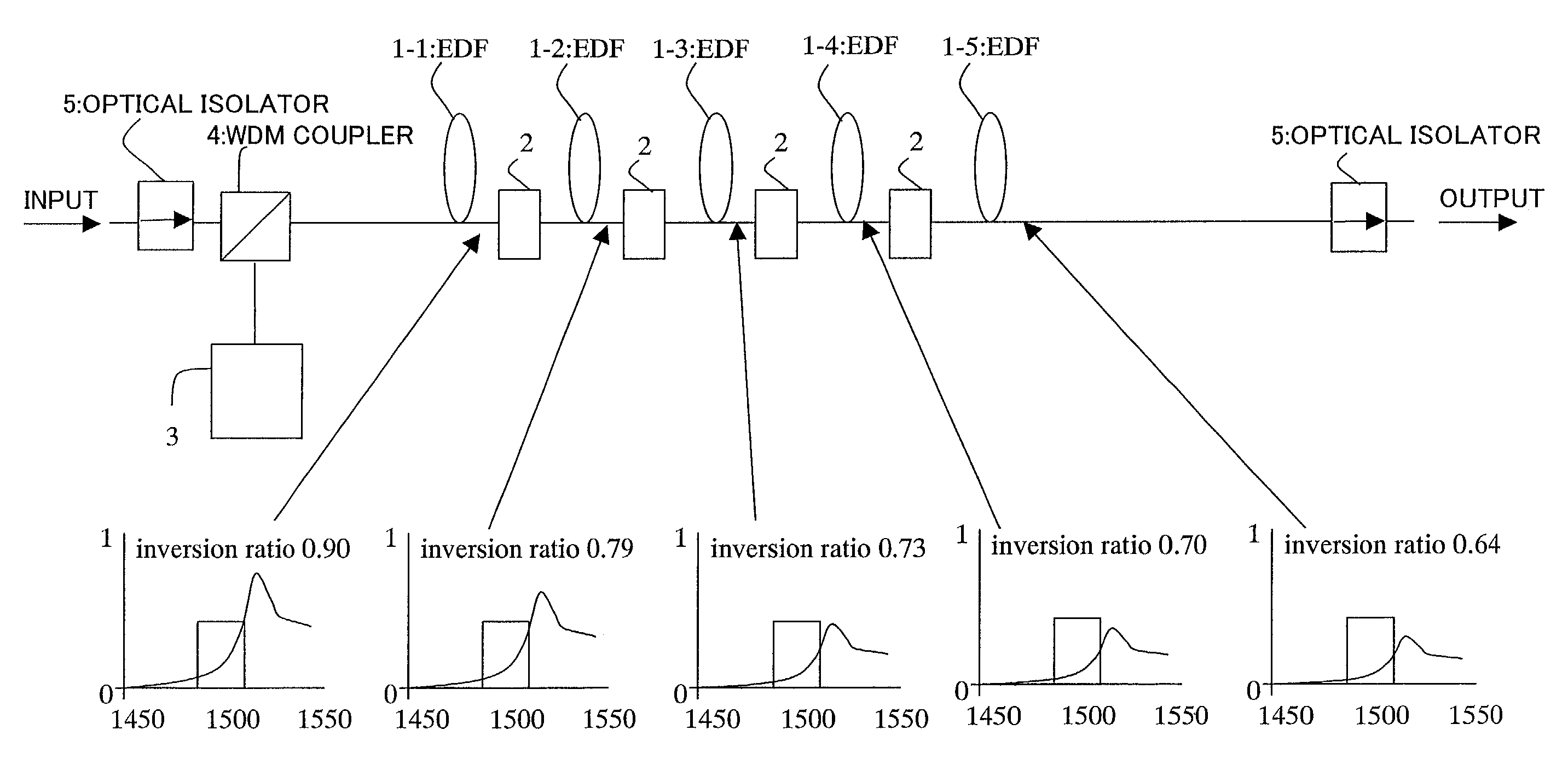
[0206]Concretely, L-band optical amplifier 56B of the present embodiment is an erbium-doped fiber amplifier (EDFA). As in the case of S-band optical amplifier 56C (see FIG. 11...


PUM

PropertyMeasurementUnit
wavelengthsaaaaaaaaaa
wavelength gainaaaaaaaaaa
wavelengthsaaaaaaaaaa

Abstract

The optical amplifier realizes EDFA amplification of optical signals in new bands (the S+- and S-bands), at wavelengths of 1450 to 1530 nm. The amplifier uses multiple erbium-doped fibers to amplify optical signals at wavelengths of 1450 to 1530 nm. Each of the multiple optical filters is interposed between the individual erbium-doped fibers. The sum of the transmission characteristics of the multiple filters is identical to an inverted EDF wavelength gain characteristic at wavelengths of 1450 to 1530 nm which is then shifted to the direction that the transmission increases.

Description

BACKGROUND OF THE INVENTION[0001]1. Field of the Invention[0002]The present invention relates to an optical amplifier suitable for use in amplifying optical signals, particularly those in newly available bands, and for use in a wavelength-division multiplexing optical transmission system, in which multiple optical signals at different wavelengths are combined to be transmitted through one optical fiber. The invention also relates to a method for compensating for gain tilts (variations) across a range of wavelengths occurring in the present optical amplifier.[0003]2. Description of the Related Art[0004]In a wavelength-division multiplexing optical transmission system (optical transmission system), which transmits wavelength-division multiplexed optical signals at different wavelengths, an optical fiber transmission path reveals low (about 0.3 dB / km or smaller) transmission loss in a limited range of wavelengths from 1450 to 1650 nm. Various types of optical amplifiers have thus been ...

Claims


Application Information

Patent Timeline
Patent Type & Authority Patents(United States)
IPC IPC(8): H01S3/00G02B6/036G02F1/35H01S3/06H01S3/067H01S3/10H01S3/16H01S3/17
CPCH01S3/06758H04B10/2525H04B10/2916H04B10/2941H01S3/0672H01S3/06775H01S3/10023H01S3/1608H01S3/173H04B2210/258H01S2301/04H04B2210/003H01S2301/02
Inventor NISHIHARA, MASATOSUGAYA, YASUSHIHAYASHI, ETSUKO
Owner FUJITSU LTD
Why Eureka
Try Eureka