

Chemical Engines and Methods for Their Use, Especially in the Injection of Highly Viscous Fluids
a technology of high viscosity and chemical engines, which is applied in the direction of fluid handling, instruments, fluid couplings, etc., can solve the problems that the power density claimed levels were not previously identified as desirable or achievable, and achieve the effects of less risk of breakage, convenient measurement, and greater comfor
- Summary
- Abstract
- Description
- Claims
- Application Information
AI Technical Summary
Benefits of technology
Problems solved by technology
Method used
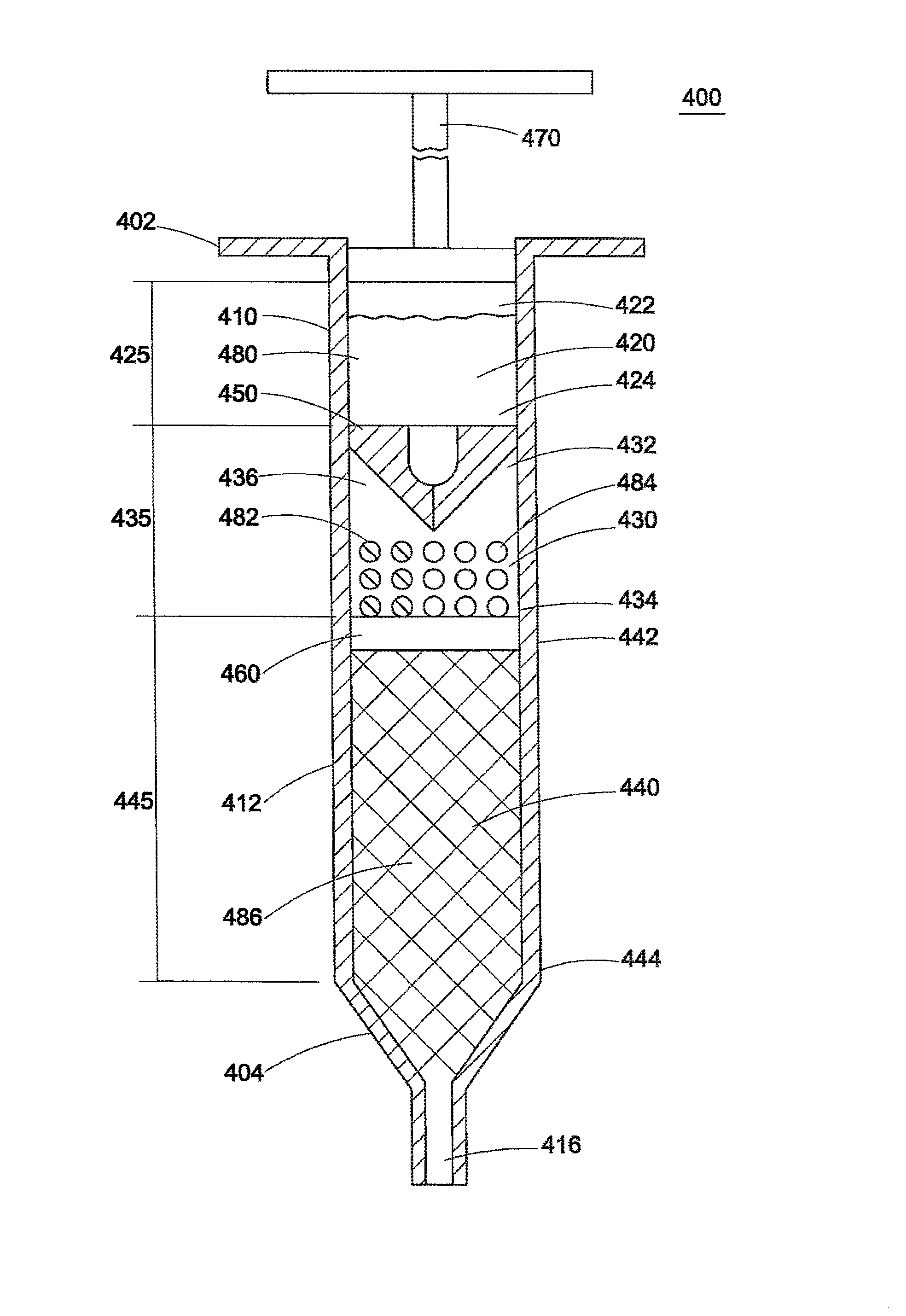
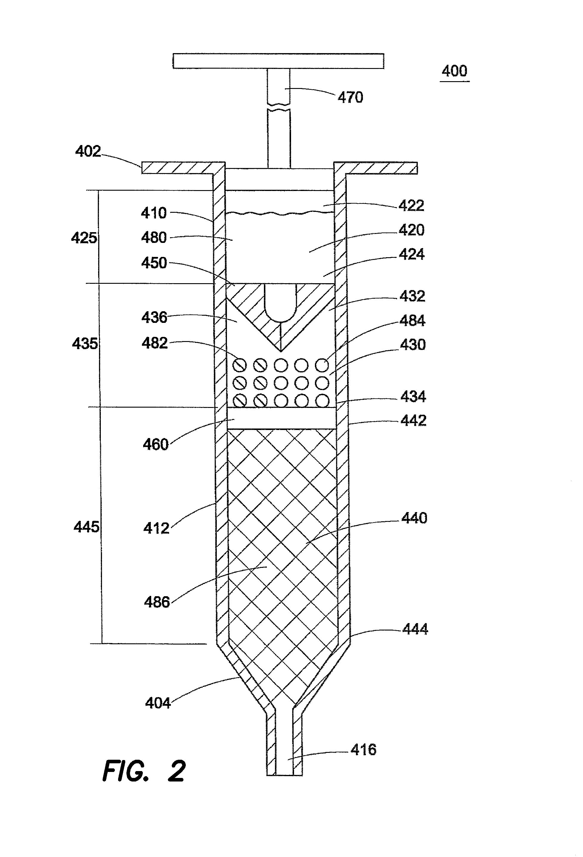
Image

Examples
example 1
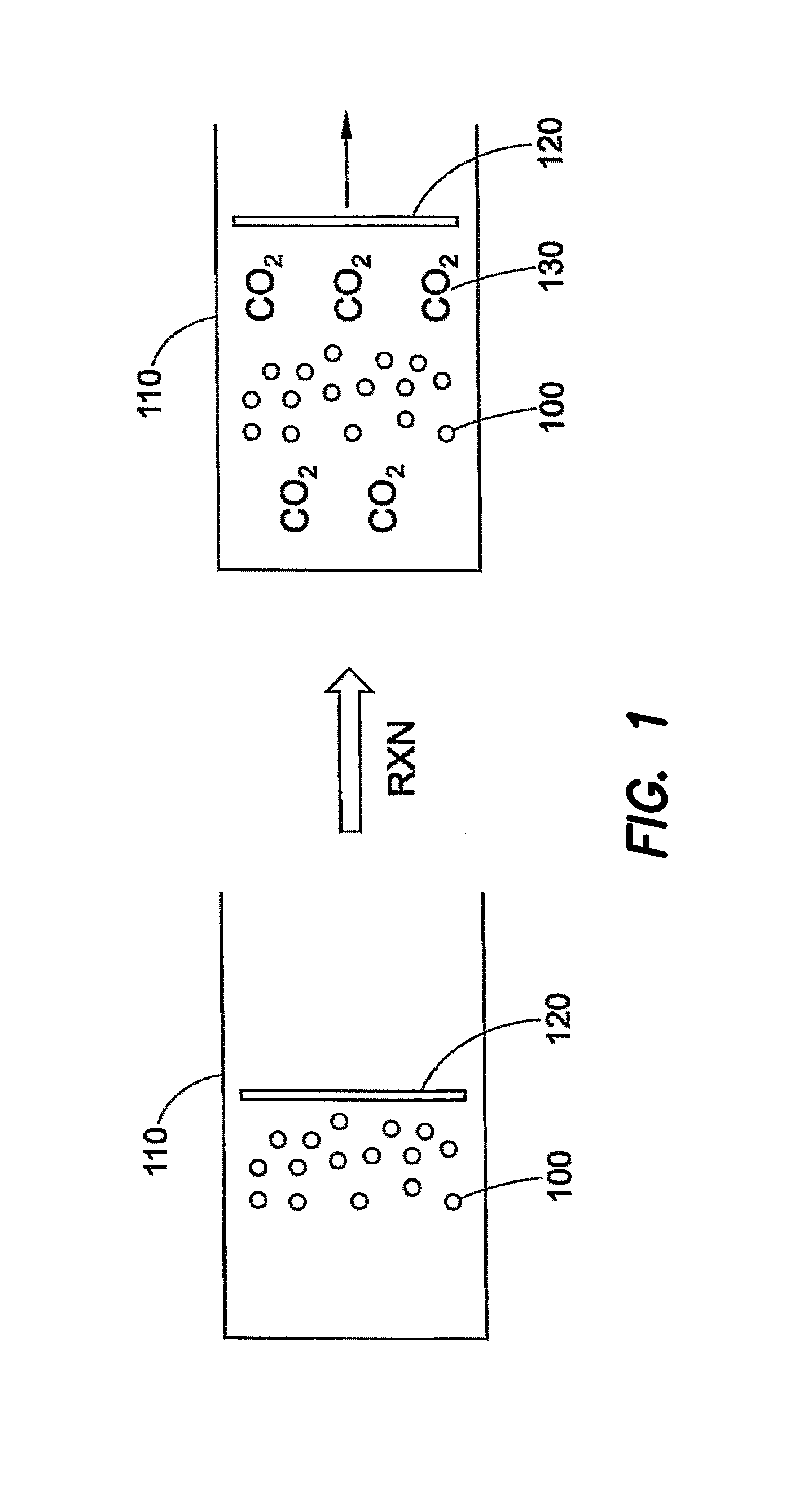
[0236]Two fluids were tested, water (1 cP) and silicone oil (73 cP). Water served as the low-viscosity fluid, silicone oil served as the high-viscosity fluid. One of these two fluids was added to the prefilled syringe 1040 depending on the experiment. To the reaction chamber syringe 1030 was added 400 mg NaHCO3 and 300 mg citric acid, as dry powders. The injector syringe 1020 was filled with either 0.1 ml, 0.25 ml, or 0.5 ml water. The water was injected into the reaction syringe 1030 (the volume of the reaction syringe was adjusted based on the volume to be delivered by the injector syringe). The delivered volume versus time and total delivery time were measured. The pressure was calculated using the Hagen-Poiseuille equation and assumed there was 0.6 lb frictional force between the stopper 1066 and the prefilled syringe 1040. Alternatively, the force on the prefilled syringe 1040 was determined by placing a load cell at the exit. The results are shown in Table 1 and were based on ...
example 2
[0239]Sodium chloride (NaCl) was used to enhance the release of gaseous CO2 from the reaction solution in the reaction chamber, accelerating the increase in pressure. In control experiments, citric acid and NaHCO3 were placed in the reaction syringe. A solution of 1.15 M NaHCO3 in water was injected into the reaction syringe from the injector syringe. The empty volume in the reaction syringe was kept constant through all experiments. In experiments demonstrating the concept, NaCl was added to the reaction syringe. The chemical reaction was used to deliver 1 ml of water or silicone oil from the prefilled syringe. The delivered volume versus time and total delivery time were measured. The pressure was calculated using the Hagen-Poiseuille equation and assumed there was a 0.6 lb frictional force between the prefilled plunger and the syringe. Note that bicarbonate was present in the water injected into the reaction syringe, so that gas could be generated even if solid bicarbonate was no...
example 3
[0241]Several different reagents were tested to show the influence of powder morphology and structure on the pressure profile. Morphology, in this case, refers to the surface area, shape, and packing of molecules in the powder. The same bicarbonate (sodium bicarbonate) was tested. Three different morphologies were created—one as-received, one freeze-dried, which was produced by freeze drying a 1.15 M solution, and one where the bicarbonate was packed into a tablet “Layering” of the reagents in the reaction chamber was also examined; where layering refers to preferential placement of reagents within the reaction cylinder. In another example, Alka Selzter, which contains citric acid and sodium bicarbonate in a matrix, was used.
[0242]The following reagents were used: as-received baking soda (NaHCO3), citric acid, freeze-dried baking soda, Alka-Seltzer, or as-received potassium bicarbonate (KHCO3). The as-received baking soda was also tested as a powder, or in a tablet form. The tablet ...
PUM
 Abstract
Description
Claims
Application Information