
Radiotherapy apparatus

a radiotherapy apparatus and apparatus technology, applied in radiation therapy, radiation therapy, x-ray/gamma-ray/particle irradiation therapy, etc., can solve the problems of reducing the tolerance of the apparatus as a whole, no longer being routine, and correspondingly more likely to indicate an error, so as to achieve the effect of improving the system control architectur

Active Publication Date: 2015-11-05
ELEKTA AB
View PDF4 Cites 0 Cited by
  • Summary
  • Abstract
  • Description
  • Claims
  • Application Information

AI Technical Summary

Benefits of technology

The invention provides a system with tighter tolerances for errors, which means that errors are less likely to occur and can be detected earlier. This means that the error-checking regime can be carried out locally for each component, rather than relying on wider error tolerances that may allow non-compliant apparatus as a whole. The invention avoids a significant level of complexity and ensures that potentially troublesome combinations are detected.

Problems solved by technology

This, in turn, means that a departure from that plan will be correspondingly more likely to indicate an error by the geometry item.
It will no longer be routine for errors to arise when a geometry item needs to accelerate or decelerate and thus the error-checking regime need not make allowances for such departures from the intended path.
In such circumstances, the combined effect of the sub-tolerance errors could take the apparatus as a whole out of tolerance.
In such a system, error-checking therefore needs to be centralised, taking into account all the reported component errors so that potentially troublesome combinations can be detected.

Method used


Image

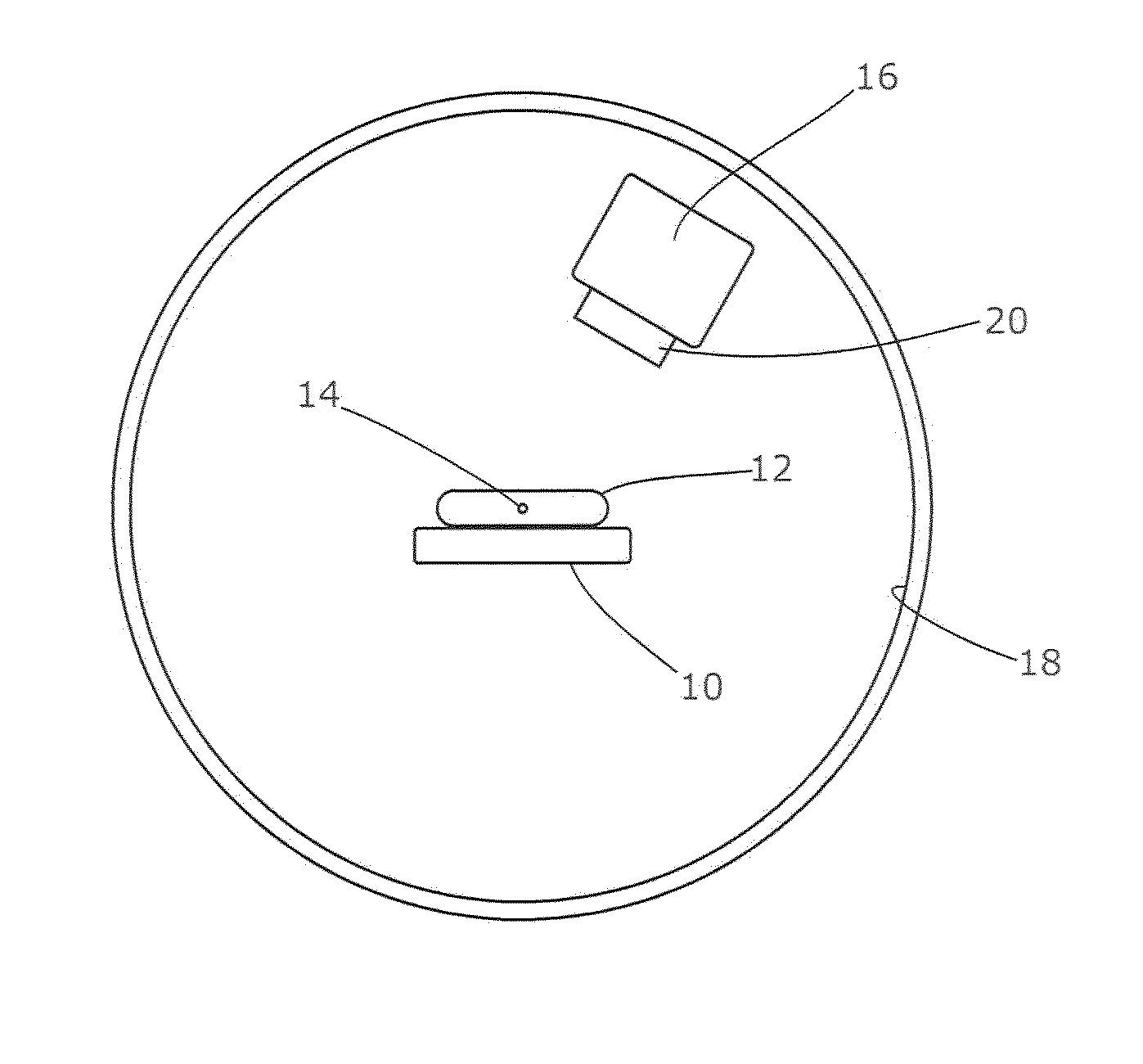
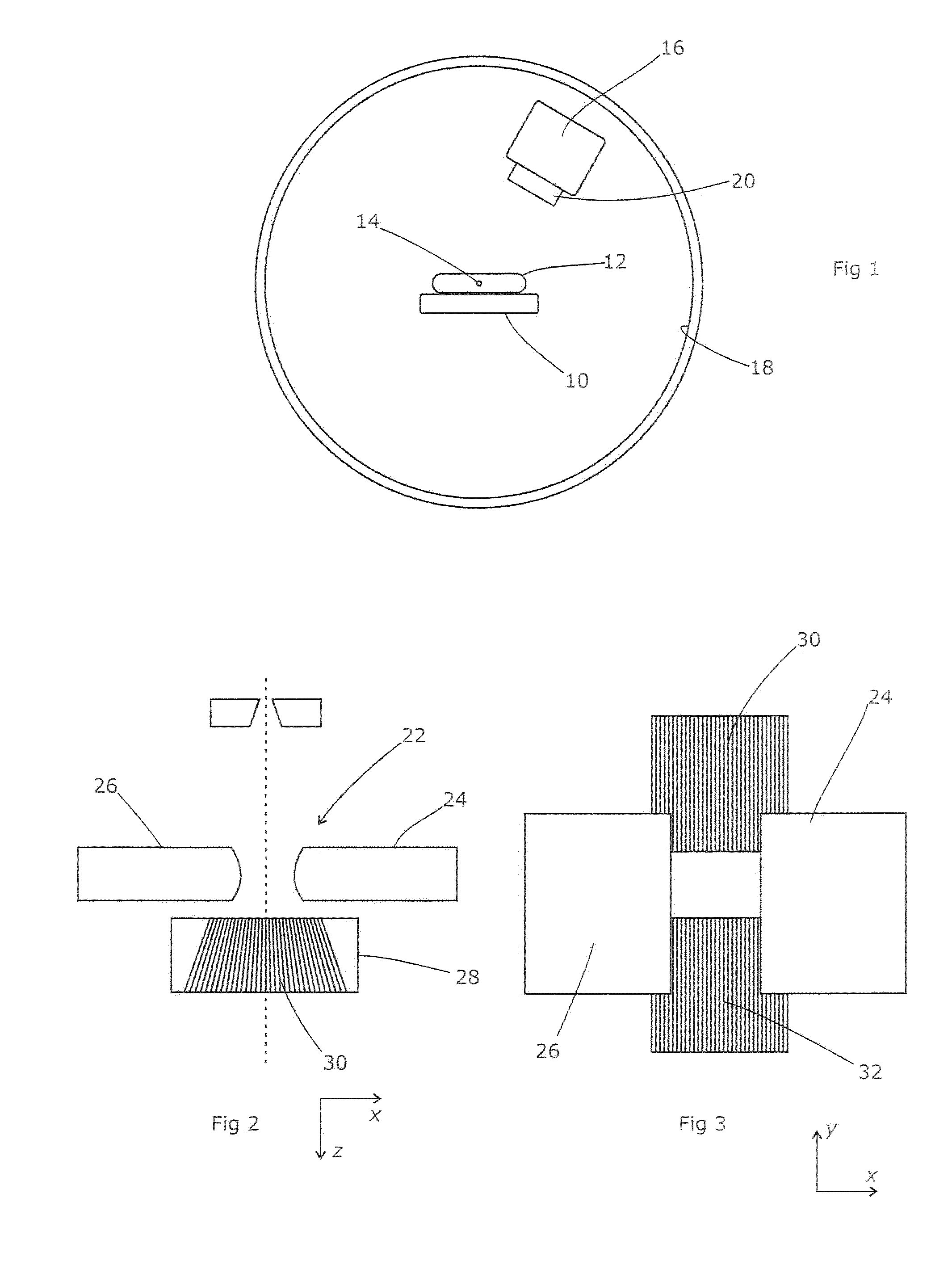
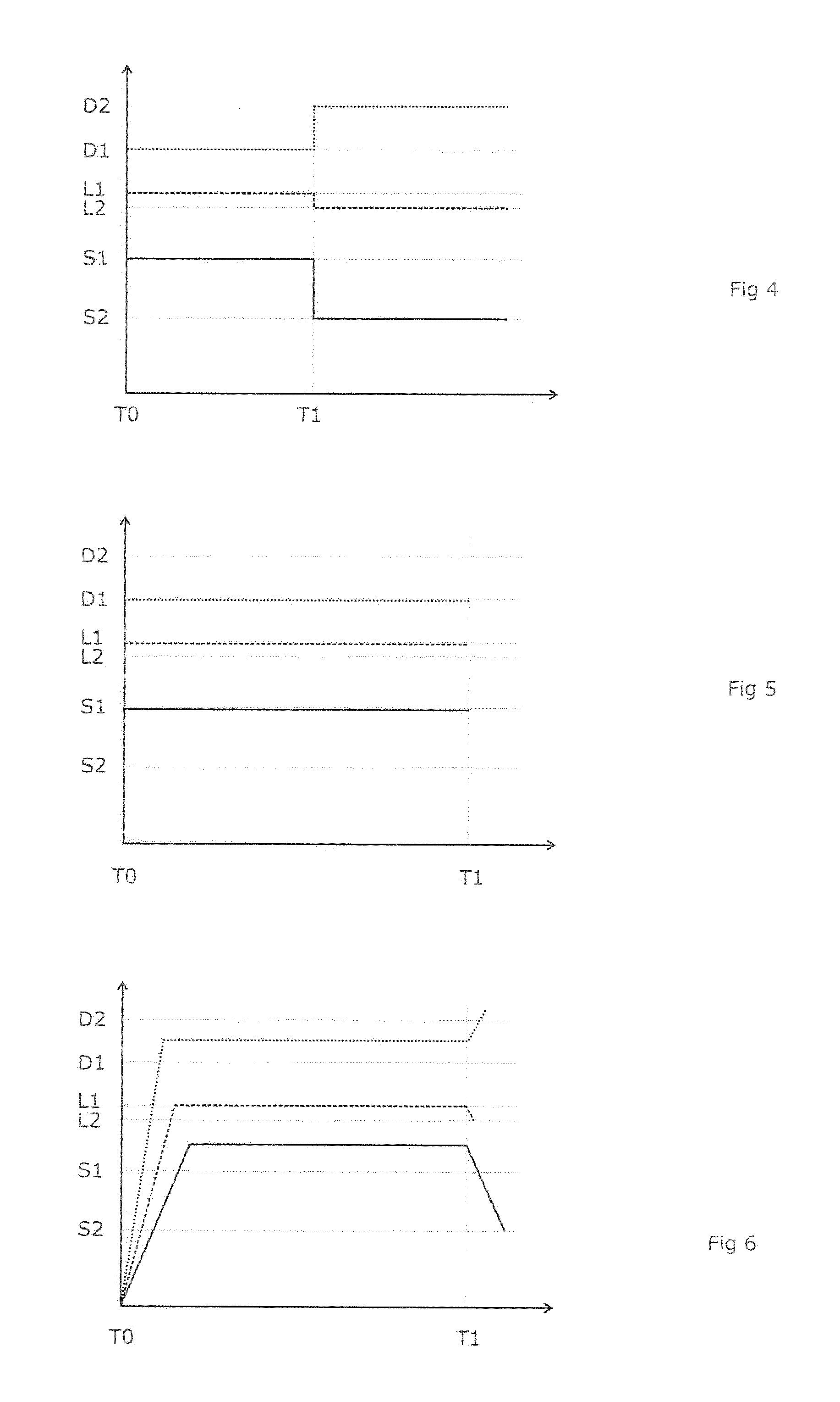
  • Radiotherapy apparatus
  • Radiotherapy apparatus
  • Radiotherapy apparatus

Examples


first embodiment

[0045]FIG. 9 shows the process flowchart for the treatment planning computer according to the present invention. This starts by accepting an intended dose profile 100 which reflects the dose profile that the clinician has prescribed, together with details of the three-dimensional structure of the patient. The latter may be in the form of a segmented CT, MRI or like form of scan, suitably registered to the coordinate system of the dose distribution. Segmentation is a process of marking a CT or MRI scan to indicate the nature of the various tissue types present within the scan, for example bone, soft tissue, tumorous tissue, water, air etc. These different tissue types have different rates of attenuation of x-rays and therefore are taken into account by the treatment planning computer. Registration is a process of aligning the scan so that it employs the same co-ordinate system as the other aspects of the system, including the dose distribution and the radiotherapy apparatus.

[0046]In ...

second embodiment

[0055]In this way, the invention creates a revised version of the treatment plan in which the inertia effects of the various elements of the radiotherapy apparatus are catered for, and as a result the treatment plan that is actually put into effect is much more closely achievable, with the advantages set out above. In the invention, the treatment plan is created ab initio with the inertial effects in mind and therefore need not be revised by the delivery control system.

[0056]FIG. 12 shows the process flowchart for the treatment planning computer according to a second embodiment of the present invention. This starts as with the first embodiment, by accepting an intended dose profile 100 which reflects the dose profile that the clinician has prescribed, together with details of the three-dimensional structure of the patient. The latter may be in the form of a segmented CT, MRI or like form of scan, suitably registered to the coordinate system of the dose distribution. In this embodime...


PUM


Abstract

A method for dealing with the effects of inertia in a radiotherapy apparatus is disclosed. The method may include catering for inertia in advance by incorporating inertia factors into an output from a delivery control system which adapts the treatment plan by incorporating the inertia factors, or by including the inertia factors as a constraint in the treatment planning process. The instructions delivered to the geometry items may reflect their inertia behavior and can therefore be followed very closely. This may indicate that a departure from that plan will be correspondingly more likely to indicate an error by the geometry item. When a geometry item needs to accelerate or decelerate, less error may arise and thus the error-checking regime may not necessarily make allowances for such departures from the intended path, thereby tightening the error tolerances. Error-checking may be safely carried out locally for each component.

Description

FIELD OF THE INVENTION[0001]The present invention relates to apparatus for radiotherapy.BACKGROUND ART[0002]Radiotherapy is a process whereby a beam of harmful radiation is directed generally towards a region of a patient, usually in order to treat a tumour within that region. The radiation causes damage to living cells in its path, and hence inhibits or reduces the tumour. It also damages healthy tissue if applied in significant doses, and therefore efforts are made to limit the dose to healthy tissues while maintaining the prescribed dose to cancerous tissue.[0003]One apparently straightforward means of limiting the dose to healthy tissue is to direct the beam towards the tumour from a plurality of different directions. Thus, the total dose delivered to the tumour can be significantly greater than the dose applied to any individual section of surrounding tissue. A common approach to doing so is to mount the radiation source on a rotateable support, with the source being oriented t...

Claims


Application Information

Patent Timeline
Patent Type & Authority Applications(United States)
IPC IPC(8): A61N5/10
CPCA61N5/1071A61N5/1081A61N5/1067A61N5/103A61N5/1048
Inventor BURT, DAVIDBOXALL, PAUL
Owner ELEKTA AB
Learn More