[0022]The above described measurement method, measurement
mask and measurement apparatus allow the performance of a directionally resolved scattered light measurement in the denotation explained previously. The solution according to the invention is based in particular upon the finding that more meaningful scattered light measurement results can be obtained if the scattered light produced is established directionally resolved. This type of directionally resolved scattered light measurement is made possible according to the invention in particular by providing both of the aforementioned measuring fields. As already mentioned, both measuring fields respectively have a second light manipulation type reference structure. The measuring fields can basically either be designed to be of the first light manipulation type or of the second light manipulation type. If both measuring fields are of the first light manipulation type, the reference structure respectively forms a second light manipulation type region of the measuring fields. If the measuring fields are of the second light manipulation type, the reference structures are respectively second light manipulation type regions in an environment which is also of the second light manipulation type. In this case the reference structure passes into its environment. The second light manipulation type measuring fields are advantageously aligned prior to
exposure using their own adjustment structures in relation to the measuring location. These types of adjustment structure can for example be designed as first light manipulation type crosses and be disposed approximately 2.0 mm from the location of the reference structure. In this embodiment every second light manipulation type measuring field should have at least one adjustment structure, preferably at the respective same location. When using first light manipulation type measuring fields with a second light manipulation type reference structure, the respective reference structure can be used to adjust the measuring fields.
[0027]In the case where scatter effects caused by multiple reflections play a large role in the optical system, a field dependency of the scattered light often occurs. In this case it is advantageous to take the scattered light measurement according to the invention at different field points. Due to the anisotropic
scanner slot geometries, scatter effects caused by multiple reflections have a highly anisotropic effect.
[0034]In an embodiment according to the invention each measuring structure is offset by maximum 2.0 mm in relation to the reference structure of the respective measuring field. In a further embodiment each measuring structure has a dimension of at least 10 μm, in particular of at least 20 μm, i.e. the measuring structure is at least in one direction at least 10 μm in size. In the case where the measuring structure is imaged using a
scanner for microlithography with a
reduction ratio of 1:4, the minimum dimension of the measuring structure in the
image plane is 2.5 μm, and in particular 5 μm. It is therefore sufficiently dimensioned in order to bring about a significant change in the
light intensity measured at the imaging location of the reference structure. The distance between the reference structure and the measuring structure on the
mask is maximum 2.0 mm, and in particular maximum 1.0 mm. In the case where the structures are imaged using the aforementioned
scanner, the distance between the reference structure and the measuring structure in the image plane is maximum 500 μm, and in particular 250 μm. It is therefore guaranteed that scattered light with a scatter range which is typically significant with lithographic images can be measured. The
minimum distance between the center points of the reference structure and the measuring structure is advantageously in the range of the minimum dimension of the measuring structure. The mask according to the invention makes it possible to implement the method according to the invention for measuring scattered light with the result of a directionally resolved scattered light measurement. The first measuring of the method according to the invention, with which the first measuring field is imaged, can be implemented using a corresponding measuring field on the same mask or on another mask.
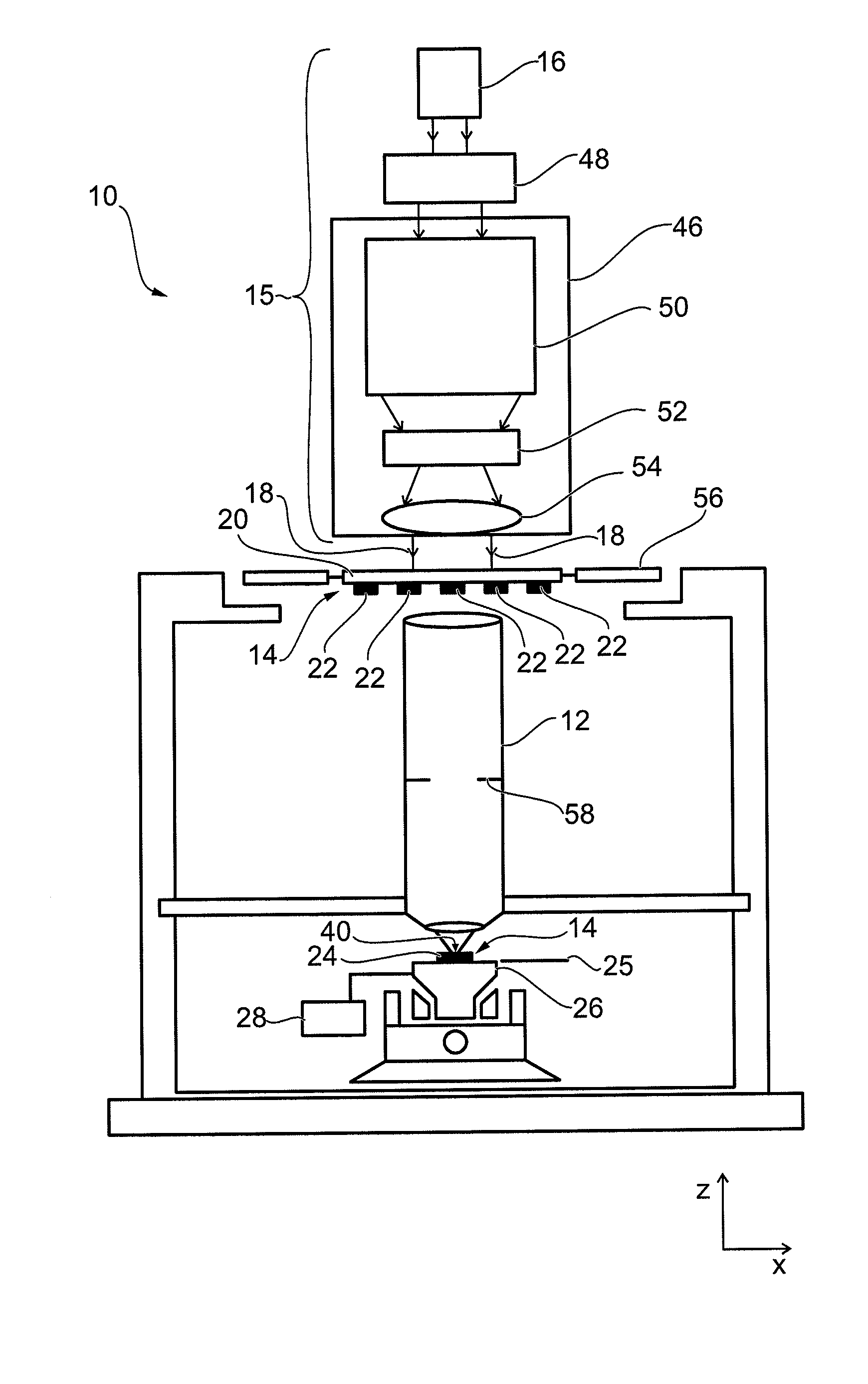
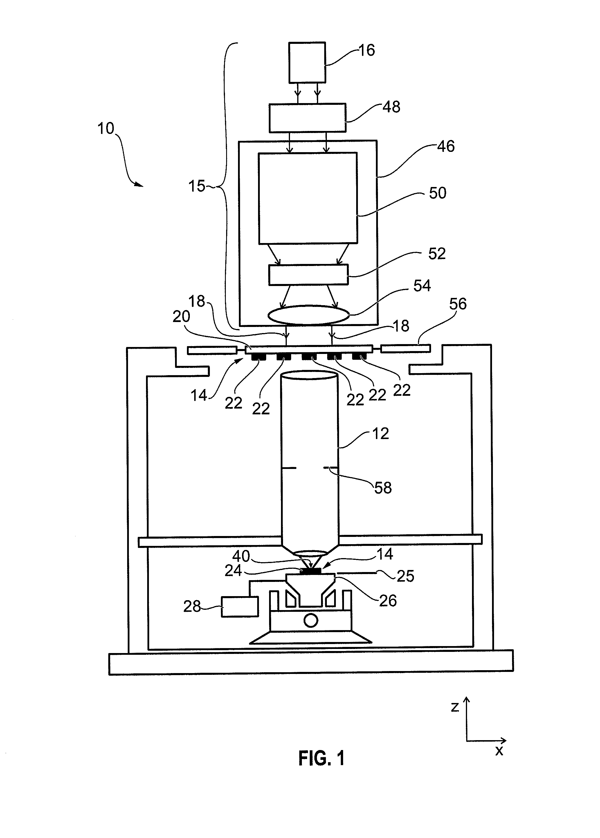
[0036]In a further embodiment according to the invention the measuring location for measuring the first and / or second light intensity is configured as a two-dimensional area having a maximum lateral dimension of at most 10 μm. Therefore the measurement area is smaller than or at the most 10 μm in any lateral direction. In a further embodiment the measurement area has a maximum lateral dimension of at most 5 μm, in particular of at most 1 μm. With the measurement area being dimensioned this way short range scattering light can be detected properly. Advantageously the measurement area is dimensioned in both orthogonal directions about the same, e.g. the measurement area is square in shape having a side length of at most 10 μm, in particular 5 μm or 1 μm. The measurement can be performed by e.g. a CCD-
detector arranged at the measuring location in the image plane. In this case a variable aperture can be used to adjust the effective measurement area on the
detector depending on the scattering range investigated. Alternatively the image at the measurement area can be magnified using a micro objective and recorded by a CCD-
detector arranged in the image plane of the micro objective. In this case the effective measurement area on the detector can be adjusted using a variable
magnification of the micro objective.
[0050]In a further advantageous embodiment the
exposure correction determined shows the necessity of eliminating
contamination in the optical system. In particular in the development stage of the
contamination an
anisotropy of the layering or of the accretion in the form of
anisotropic scattering is visible, even before the whole surface is contaminated homogeneously (for example in monolayers etc.), and this can be demonstrated in a known way
through transmission loss. The method according to the invention therefore enables early identification of surface
contamination which primarily comes to light in
anisotropic scattering, and would only become noticeable secondarily
through transmission loss. Therefore the method according to the invention enables early identification of contamination.
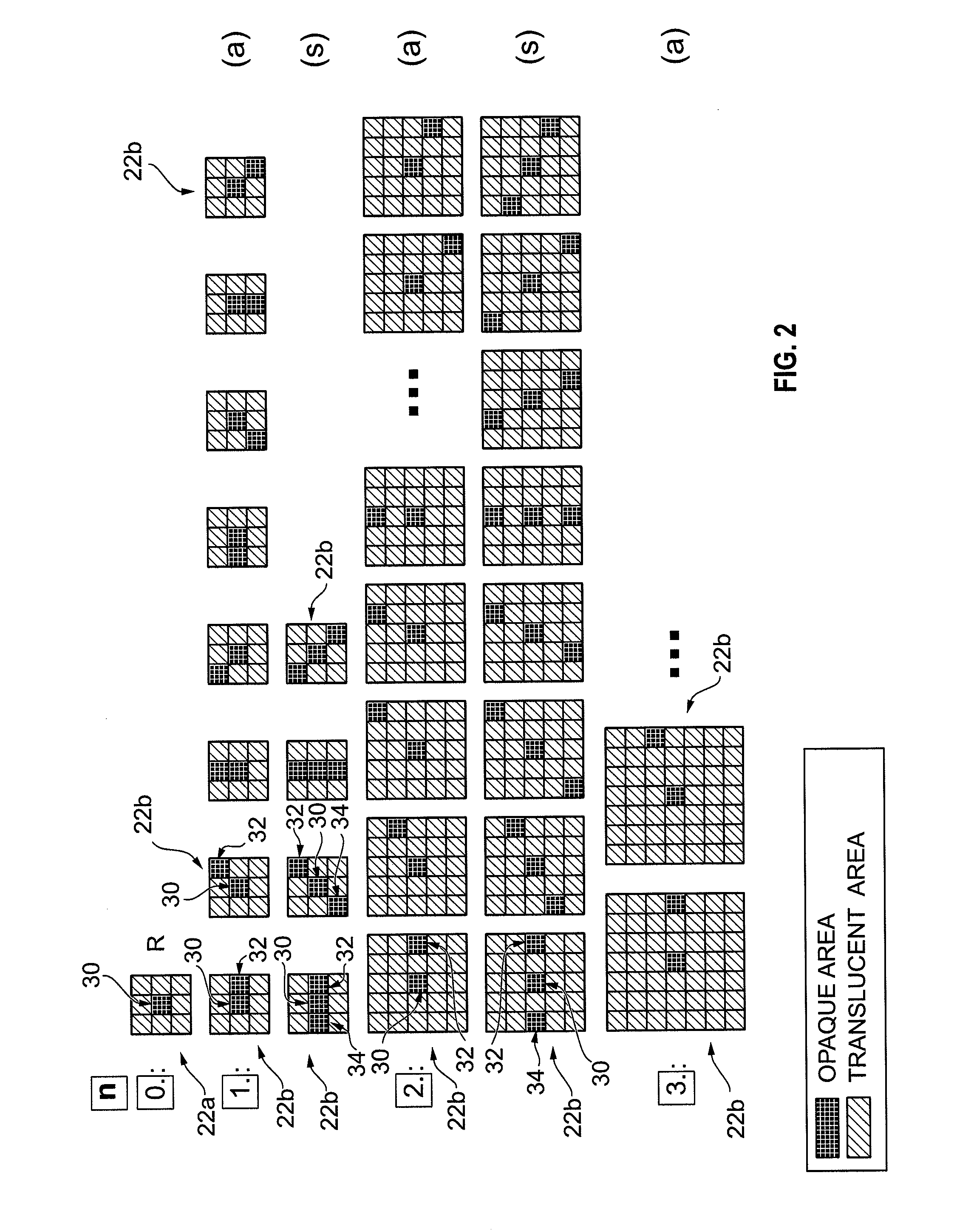
[0058]In a further embodiment according to the invention the measuring structure and / or the respective reference structure have the shape of a polygon, in particular the shape of a tetragon or a
square shape. In a further embodiment according to the invention the respective reference structure is disposed in the center of the corresponding field. In particular, the reference structure is disposed at the location of the area center of the corresponding field. This arrangement of the reference structure leads to the measuring location also being disposed centrally in the image of the measuring field. It is therefore possible to dispose the measuring structures in the individual measuring fields in different directions respectively the same distance away from the corresponding reference structure, and so to take a directionally resolved scattered light measurement based upon uniform scatter ranges. Furthermore, it is guaranteed by the central positioning of the reference structure that scattered
light effects from outside the measuring field reach the measuring location as isotropically as possible. This reduces the error tolerances in the directionally-resolved scattered light measurement result.

