Holder product range and cleaning apparatus for cleaning breathing apparatuses

a technology of breathing apparatus and cleaning apparatus, which is applied in the direction of cleaning equipment, cleaning using liquids, underwater equipment, etc., can solve the problems of hardly being standardized, the cleaning of modified laundry washing machines is equally comparatively time-consuming in practice, and the manual cleaning of breathing apparatuses is very labor-intensive. , to achieve the effect of saving heating energy, facilitating the drying process, and maximizing the utilization of drying cabinets

Active Publication Date: 2015-11-05
MEIKO MASCHENBAU
View PDF1 Cites 20 Cited by
  • Summary
  • Abstract
  • Description
  • Claims
  • Application Information

AI Technical Summary

Benefits of technology

[0112]As a result of the special realization of the product range of holders, all surfaces of the breathing apparatuses can be moistened very well by the cleaning fluid. The cleaning fluid can be recirculated and / or sprayed by nozzles, for example. The mechanical action of the nozzle jets can be supported by an optimum holder.
[0113]The cleaning fluid, for example the wash fluid, is able to drain unobstructed from all sides of the parts to be cleaned such that the contaminants are able to be removed entirely. As a result of the cleaning fluid draining well, a subsequent drying process can be made considerably easier and consequently also shortened. In practice this means, along with a time saving, better utilization of the drying cabinets and a saving in heating energy per breathing apparatus dried.

Problems solved by technology

Thus, manual cleaning of the breathing apparatuses is very labor-intensive.
In addition, the cleaning process in this case is strongly influenced by the individual cleaning force and as a result can hardly be standardized.
Cleaning in modified laundry washing machines is, however, equally comparatively time-intensive in practice.
In addition, the breathing apparatuses or the component parts thereof are in many cases filled with cleaning fluid in the interior after cleaning, as they are either arranged randomly in the drum of the washing machine or as their position inside the drum is fixed and cannot be influenced in a targeted manner such that, as a result, the breathing apparatuses cannot drain when the cleaning procedure ends.
Accessory parts cannot be cleaned for the most part in the washing machine at the same time as individual association is frequently lost during the process.
The cleaning method made known from DE 10 2007 012 768 B4, in contrast, comprises the above-described disadvantages and is comparatively expensive.
In addition, the device shown does not enable simultaneous cleaning and, where applicable, disinfection of breathing valves and protective breathing masks as well as accessory parts.
Washers from the medical environment which have been adapted for mask cleaning are not suitable for cleaning and sufficiently sterilizing breathing valves.
Cleaning of breathing apparatuses by means of the devices shown is generally not possible or only possible with difficulty.
However, a disadvantage of such types of immersion methods is that complex holders with corresponding actuators are necessary in order to ensure that cleaning fluid is removed from the various cavities after cleaning as a result of corresponding movements.
However, individual assignment and cleaning of the accessory parts of the masks is not possible by means of the disclosed device.
In addition, the cleaning of gas-conducting elements, such as for example breathing valves, is not possible using the disclosed device.
This device is not suitable either, in principle, for cleaning gas-conducting elements and accessory parts.
However, a disadvantage of the device shown is that cleaning liquid can penetrate into gas-conducting regions.
Accordingly, in many cases a cleaning or disinfection result may not be optimum and can be highly variable.

Method used


Image

  • Holder product range and cleaning apparatus for cleaning breathing apparatuses
  • Holder product range and cleaning apparatus for cleaning breathing apparatuses
  • Holder product range and cleaning apparatus for cleaning breathing apparatuses

Examples


Embodiment Construction

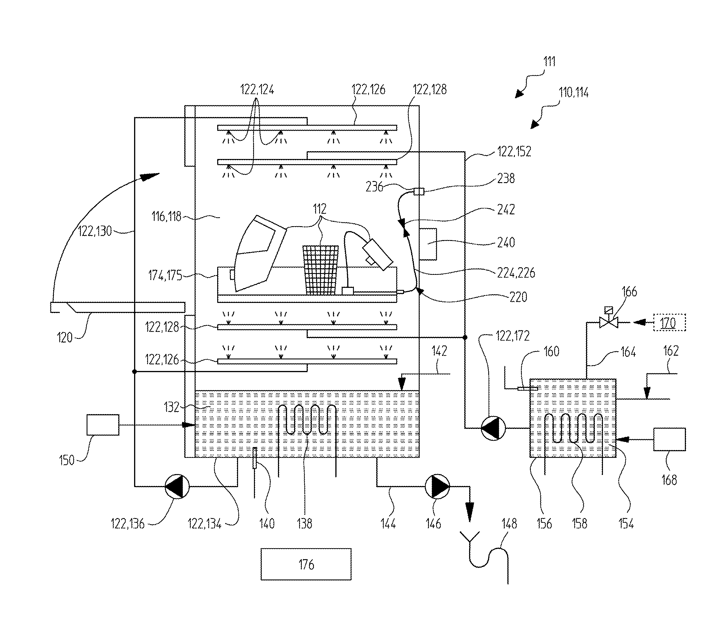
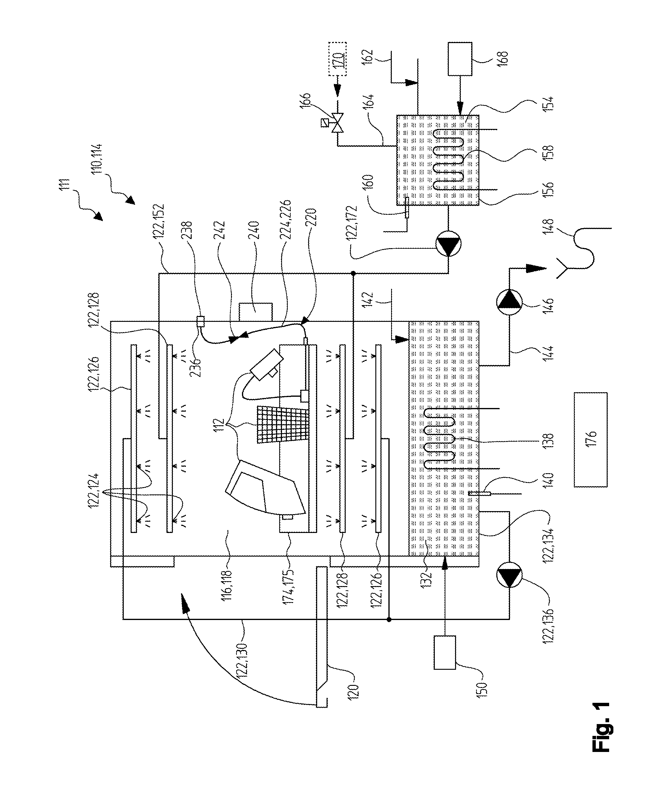
[0129]FIG. 1 shows an exemplary embodiment of a cleaning apparatus 110 which is set up for cleaning one or several breathing apparatuses 112 and which is a component part of a cleaning system 111 according to the invention. The cleaning apparatus 110 is shown schematically in a sectional representation in FIG. 1. The cleaning apparatus 110 can be developed, for example, as a washer 114. The cleaning apparatus 110 includes a cleaning chamber 116, for example a wash chamber 118. Said cleaning chamber 116 can be opened, for example, by a door 120, for example a hinged door, a sliding door or a flap, and / or by another opening device. As an alternative to this or in addition to it, the cleaning chamber 116 can also be developed as a cleaning chamber that is covered by a cover. Other developments are also possible. In the exemplary embodiment shown in in FIG. 1, the washer 114 is developed for example as a front loader washer. However, other developments are also possible.

[0130]The cleani...


PUM


Abstract

Proposed is a product range for cleaning breathing apparatuses, including at least two holders, wherein the holders include:
    • a first holder for cleaning breathing masks and breathing valves, including at least one mask holding device for positioning at least one breathing mask, additionally comprising at least one breathing valve holding device for positioning at least one breathing valve and least one pressurizing device with at least one pressure connection, wherein the pressure connection is connectable to the breathing valve and wherein the pressurizing device is set up to apply compressed air to the breathing valve during cleaning; and
    • at least one second holder for cleaning carrying frameworks for pressurized gas cylinders for breather apparatuses, including at least one carrying framework holding device for positioning at least one carrying framework.
The holders are dimensioned in such a manner that they can be moved into a cleaning apparatus for cleaning the breathing apparatuses so as to be exchangeable.

Description

SCOPE OF THE INVENTION[0001]The invention relates to a product range of holders for breathing apparatuses as well as to a cleaning apparatus and to a method for cleaning breathing apparatuses. These types of product ranges, cleaning devices and methods are generally used for cleaning and as an option also additionally for sterilizing and / or disinfecting breathing apparatuses or also components parts of the same. In general, the devices and methods described within the framework of the present invention can be used, for example, to clean breathing apparatuses for rescue teams such as the fire service, technical relief organizations or paramedics. As an alternative to this or in addition to it, breathing apparatuses for divers or in general persons in hostile or critical working environments can also be cleaned. Consequently, the devices and methods according to the present invention can also be used, for example, within the framework of use by armed forces and security forces such as...

Claims


Application Information

Patent Timeline
Patent Type & Authority Applications(United States)
IPC IPC(8): B08B5/02B08B13/00B08B3/02
CPCB08B5/02B08B13/00B08B3/02B08B3/04B08B5/00A61L2202/24A61L2202/17A61L2/18A61M16/06A61M2209/10B08B9/0328B63C11/02
Inventor FALK, HERBERTWORNER, HEIKO
Owner MEIKO MASCHENBAU
Why Eureka
Try Eureka