
Proppant Mixtures

a technology of proppant mixture and proppant, which is applied in the direction of fluid removal, chemistry apparatus and processes, and wellbore/well accessories, etc., can solve the problems of fines, proppants to fail and generate fines, and embedding of proppant packs into the faces of created fractures, so as to reduce the crushing of proppants and reduce the amount of created fines , the effect of restricting the movement of fines

Active Publication Date: 2015-11-05
PREFERRED TECH
View PDF7 Cites 11 Cited by
  • Summary
  • Abstract
  • Description
  • Claims
  • Application Information

AI Technical Summary

Benefits of technology

The invention is a method for creating a propped fracture field for oil and gas production. It uses a combination of proppants to reduce fines (small particles) generation from crushed proppants. This helps to maintain conductivity over a longer period of time. The method can introduce a mixture of first and second proppants, or sequentially introduce them. A segmented structure of proppants can be used to control fines movement and also inhibit the migration of produced fines. The invention also results in a reduction of crushing and intermittent segments of a stronger proppant to restrict fines movement, and the stronger proppant also bonds with other adjacent proppants. With this method, a conductive pathway can be created through the fracture field for a longer period of time.

Problems solved by technology

Fines are a problem in hydraulic fracturing of wells to recover trapped oil and gas.
The substantial pressures and harsh environment within the field can also cause proppants to fail and generate fines, particularly during cyclic shut-in periods.
The high stress exerted on the proppant pack can also lead to the embedment of the proppant pack into the faces of the created fractures.
These fine materials will increase in concentration as they move along the fracture toward the wellbore and can ultimately clog desirable pore openings and channels to the detriment of the well's conductivity.
It is not designed nor can it be expected to address the generation of fines (from proppant crushing) or the control of movement of the fines (that are in the packed fracture) during production of the well.

Method used


Image

  • Proppant Mixtures

Examples


examples 1-10

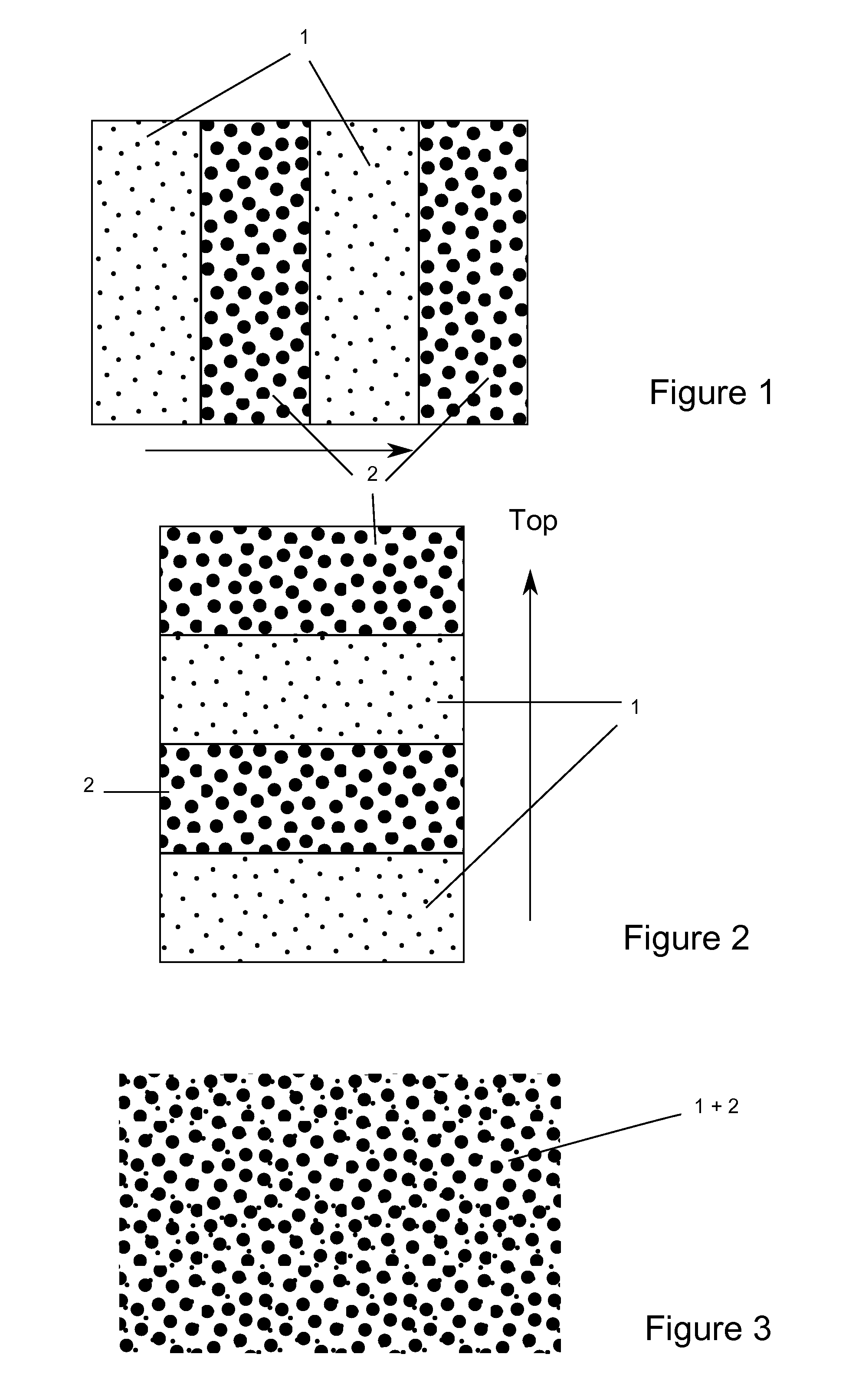
[0055]Examples 1-10 demonstrate the effects on crush resistance when mixing uncoated proppant sands with coated proppant sands in the same fracture field. Each type of proppant sand is premeasured to fall within a 20 / 40 mesh size that is typical for proppant sands. Examples 1-4 show the effects of mixing these disparate proppants substantially uniformly. Examples 5-8 demonstrate the effects of a layered structure such as would be formed after sequentially introducing the disparate proppants into the same fractured field. Each test was performed twice in a simulated fracture field by preparing representative samples of each and subjecting the sample to 10,000 psi to simulate the pressures typical of deep wells. At the end of each test, the sample was recovered and tested for the formation of undersized fines. Table 1 summarizes the pertinent data.

TABLE 1%Ratio ofCrushedAvg %Crushedat 10kCrushed atto 100%Ex.StructureProppantpsi10k psiUncoated1Mixed80% uncoated +15.94%16.040.5920% coat...


PUM

PropertyMeasurementUnit
particle sizeaaaaaaaaaa
pressuresaaaaaaaaaa

Abstract

The invention relates to a propped, fractured, subterranean field with (a) a first proppant and (b) a second proppant that exhibits a relatively higher average crush strength and / or an ability to form a particle to particle bonded structure than the first proppant. Preferably, the first proppant is uncoated sand and the second proppant is resin-coated sand. The proppants can be deposited as a substantially homogeneous mixture or in layered structures (vertical or horizontal) within the fractured field. Deformation of the second proppant under closure stress acts to spread out the compression pressures in a mixture so as to reduce failure of the first proppant. Similar protective effects are found when the proppants are deposited in layers. When formed as vertical pillar structures, the second proppant structures can also act as in-situ screens that inhibit formation fines from migrating through the proppant pack to the detriment of field conductivity.

Description

FIELD OF THE INVENTION[0001]The invention relates to mixed, layered or sequential proppant structures in a subterranean field for the reduction of proppant crushing and control of fines movement along the fractured, propped field. The invention relates to the use of mixed proppants, or the layered or sequential addition of two or more proppants. The resulting packed fracture configuration is more resistant to proppant crushing and better control of fines migration that can reduce the packed fracture's ability to maximize well productivity.BACKGROUND OF THE INVENTION[0002]Several high strength proppants are available on the market. While these proppants have superior crush strength relative to frac sand, they are considerably more expensive so the question presented to the producer is one of pure economics balancing proppant failure against cost and productivity. In some cases, the economics of using the superior proppant may be marginal so alternative methods become attractive. One ...

Claims


Application Information

Patent Timeline
Patent Type & Authority Applications(United States)
IPC IPC(8): E21B43/267C09K8/80E21B43/26
CPCE21B43/267C09K8/805E21B43/26C09K8/56C09K8/80
Inventor MCDANIEL, ROBERT RAY
Owner PREFERRED TECH
Learn More