Torsional Vibration Damper

Active Publication Date: 2015-11-05
ZF FRIEDRICHSHAFEN AG
View PDF4 Cites 12 Cited by
  • Summary
  • Abstract
  • Description
  • Claims
  • Application Information

AI Technical Summary

Benefits of technology

[0017]When the spacers extend through the respective holder at the stop, this can be carried out with an axial offset between the axis of the respective spacer and the axis of the respective holder. Owing to this axial offset, a free space results between the holder and the respective spacer. This free space promotes an elasticity at the stop in that the wall of the holder impinged by a damper mass can extend elastically into this free s

Problems solved by technology

As soon as the centrifugal force has dropped below the weight force, the damper masses

Method used


Image

  • Torsional Vibration Damper
  • Torsional Vibration Damper
  • Torsional Vibration Damper

Examples


Embodiment Construction

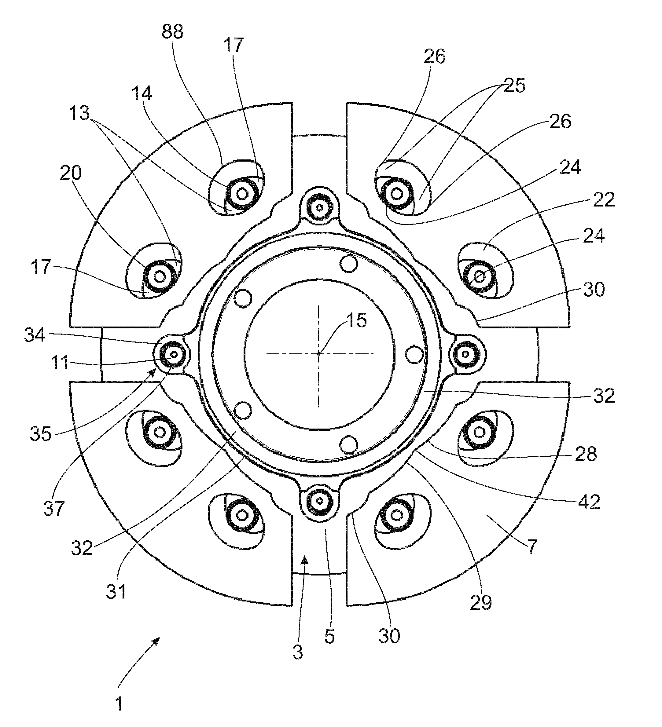
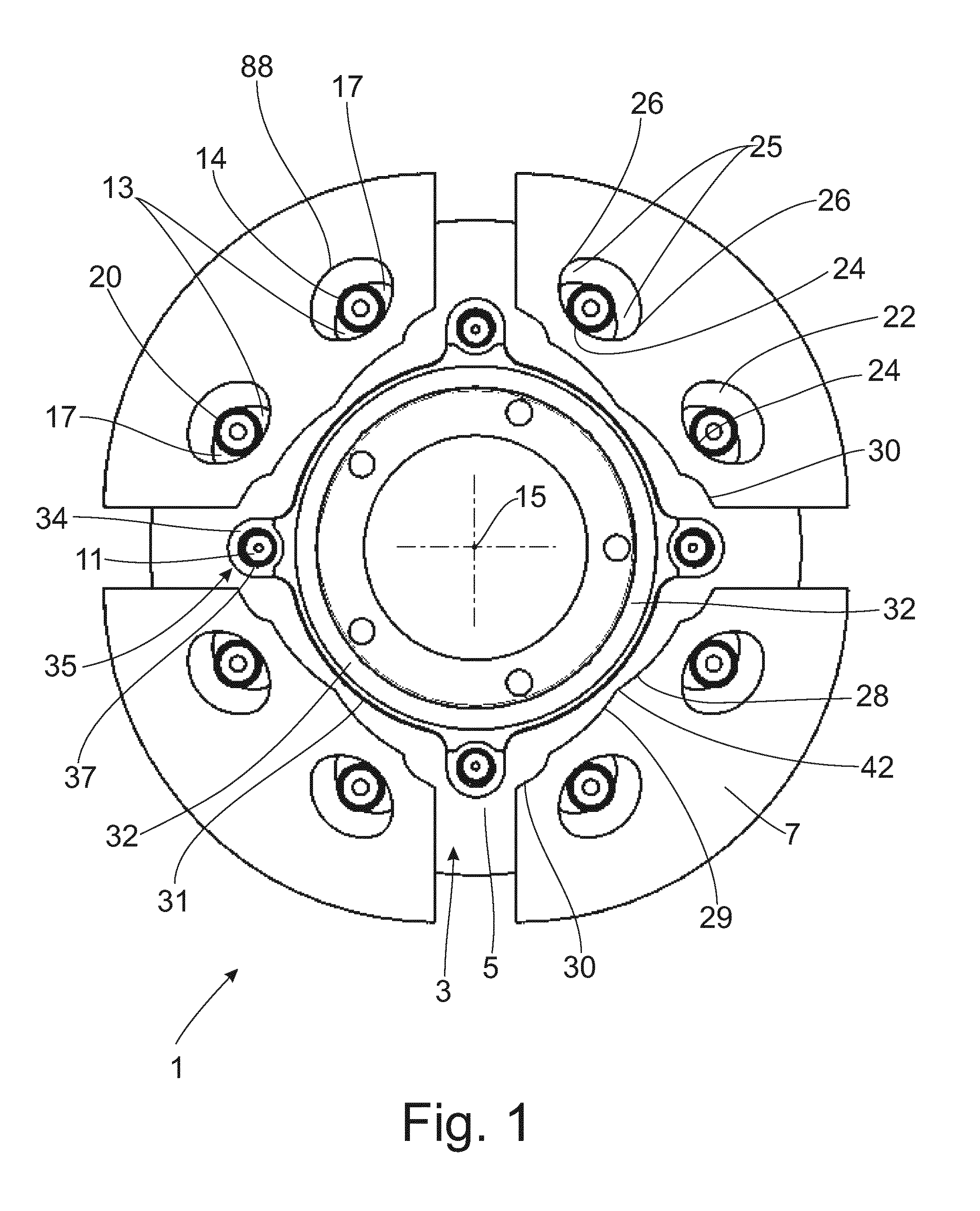
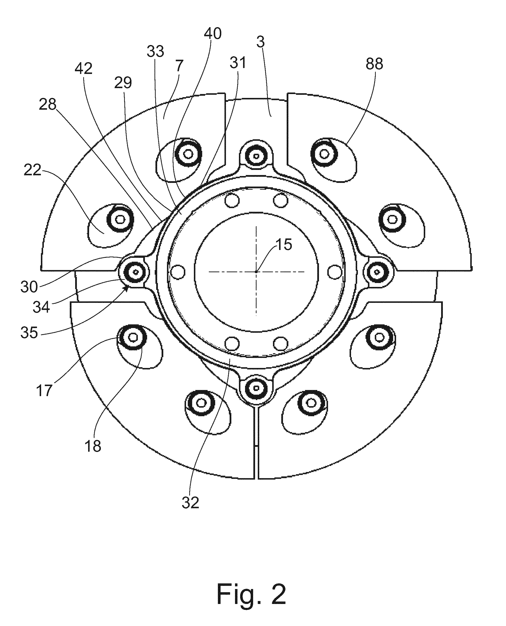
[0042]FIG. 1 shows a torsional vibration damper 1 with a damper mass carrier 3 that has two axially spaced damper mass support elements 5, of which only the damper mass support element 5 arranged axially behind the damper masses 7 is shown for the sake of a clearer illustration of a plurality of damper masses 7 received at the damper mass carrier 3. The two damper mass support elements 5 are connected to one another by spacers 11. The two damper mass support elements 5 and one of the spacers 11 are also shown in FIG. 5 or FIG. 10, which also contains information pertaining to the damper mass 7. Accordingly, the damper mass 7 has, in axial direction, a plurality of damper mass elements 44a to 44c arranged over rolling bodies 20 inside guideways 22 (see FIG. 2), specifically in such a way that the guideways 22 allow a radial relative movement of the damper mass elements 44a to 44c with respect to the spacers 11. The damper mass elements 44a to 44c have, at their radial inner sides, st...


PUM


Abstract

A torsional vibration damper is provided with a damper mass carrier at which is received at least one damper mass that is movable relative to the damper mass carrier and at least one stop. The at least one stop is associated with each stop side of the at least one damper mass. The at least one damper mass and the stop have an extension in extension direction of a central axis. The at least one damper mass has a plurality of damper mass elements in extension direction of the central axis, while the stop has in extension direction of the central axis a stop profile at its side facing the stop sides of the damper mass elements. The stop profile has different radial distances from the central axis in association with the damper mass elements.

Description

CROSS REFERENCE TO RELATED APPLICATIONS[0001]This is a U.S. national stage of application No. PCT / EP2013 / 070305, filed on Sep. 30, 2013. Priority is claimed on German Application No.: DE102012219738.9, filed Oct. 29, 2012, the content of which is incorporated herein by reference.BACKGROUND OF THE INVENTION[0002]1. Field of the Invention[0003]The present invention is directed to a torsional vibration damper that has a damper mass carrier having at least one damper mass movably received relative to the damper mass carrier and at least one stop. At least one stop is associated with each stop side of the at least one damper mass, and the at least one damper mass and the stop have an extension in direction of a central axis.[0004]2. Detailed Description of Prior Art[0005]A torsional vibration damper is known from DE 10 2009 042 818 A1. According to FIG. 1, this torsional vibration damper has, in a radially inner region, an annular component part secured to an output-side flywheel mass of...

Claims


Application Information

Patent Timeline
IPC IPC(8): F16F15/14F16F15/131
CPCF16F15/145Y10T74/2128F16F15/13128
Inventor WIRACHOWSKI, MICHAELKRAM, MATTHIASDONG, YINGSTAMPF, VOLKERSUDAU, JORGSTURMER, ARMINKOKOTT, FRIEDRICHSASSE, CHRISTOPHPITTNER, DANIELANDRES, OLIVERVIERNEUSEL, SIMONEEGLER, DENNISSIEMENS, KYRILL
Owner ZF FRIEDRICHSHAFEN AG
Why Eureka
Try Eureka