
Automated drilling fluid analyzer

a fluid analyzer and automatic technology, applied in the field of automatic meters, can solve the problems of inaccurate measurement, inability to accurately determine the viscosity of the fluid downhole, and inability to accurately measure the electrodes and the meter

Active Publication Date: 2015-11-05
SHCLUMBERGER NORGE AS
View PDF11 Cites 16 Cited by
  • Summary
  • Abstract
  • Description
  • Claims
  • Application Information

AI Technical Summary

Benefits of technology

The patent describes an invention with certain benefits. These benefits may be explained in another section.

Problems solved by technology

Typically, to measure the electrical stability of drilling fluid using the above manual probe method, the drilling fluid and associated fluid is kept static, as movement and shifts in the fluids of the drilling fluid may cause the measurements taken by the electrodes and recorded by the meter to be skewed.
While such measurement techniques give operators a general idea as to the viscosity, due to the manual implementation, the results may not always be accurate.
Additionally, the viscosity of the fluid downhole is not truly known, because the fluid cannot be heated or measured under pressure.

Method used


Image

  • Automated drilling fluid analyzer
  • Automated drilling fluid analyzer
  • Automated drilling fluid analyzer

Examples


Embodiment Construction

[0034]In one aspect, embodiments disclosed herein relate to an automated meter to measure emulsion stability and rheological properties of drilling and completion fluids. More specifically, embodiments disclosed herein relate to autonomous analysis of drilling and completion fluids that may be performed or analyzed remote from the rig or testing site.

[0035]Embodiments disclosed herein relate to a method and apparatus for automating the measurement of properties of invert emulsion oil-based or synthetic-based fluids (i.e., drilling fluids and / or completion fluids) and water based fluids. Although the disclosure herein may reference drilling fluid, one of ordinary skill in the art will appreciate that other types of fluids (e.g., completion fluids) may also be tested with the method and apparatus disclosed herein.

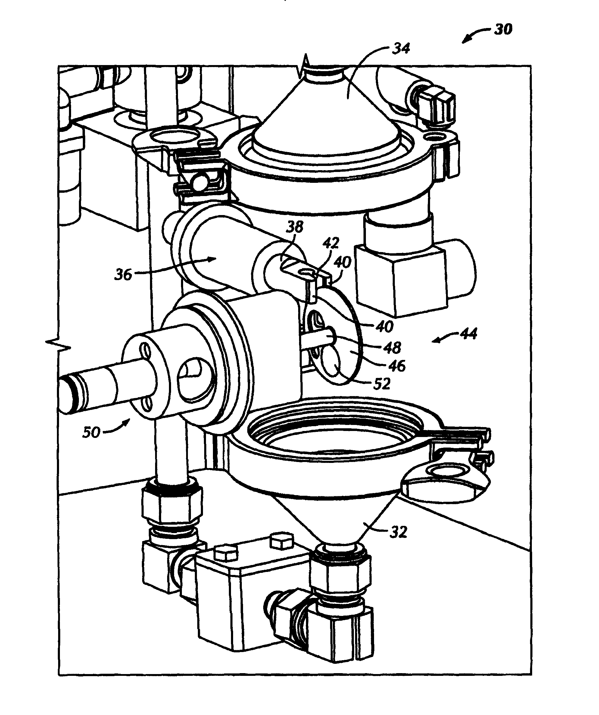
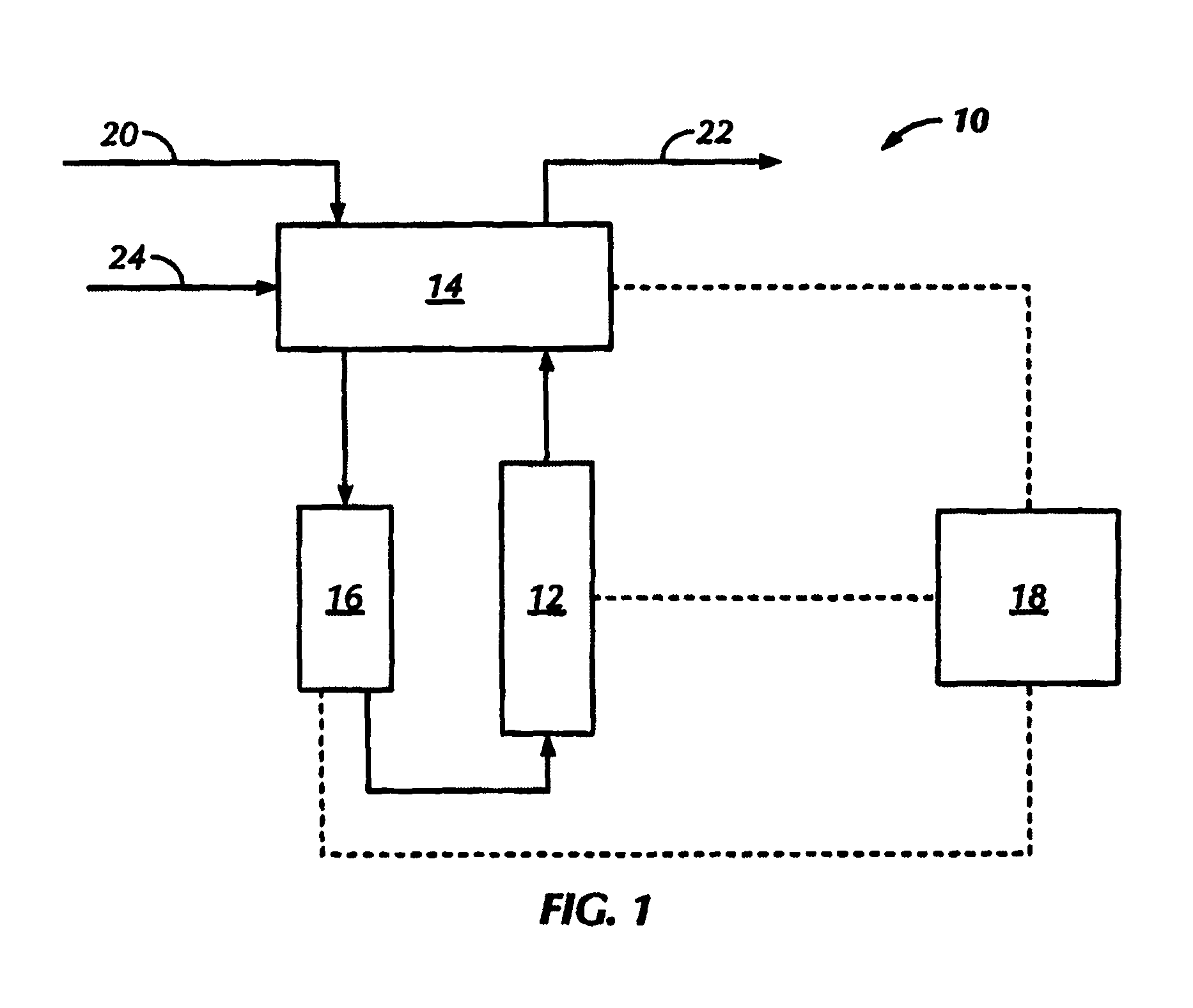
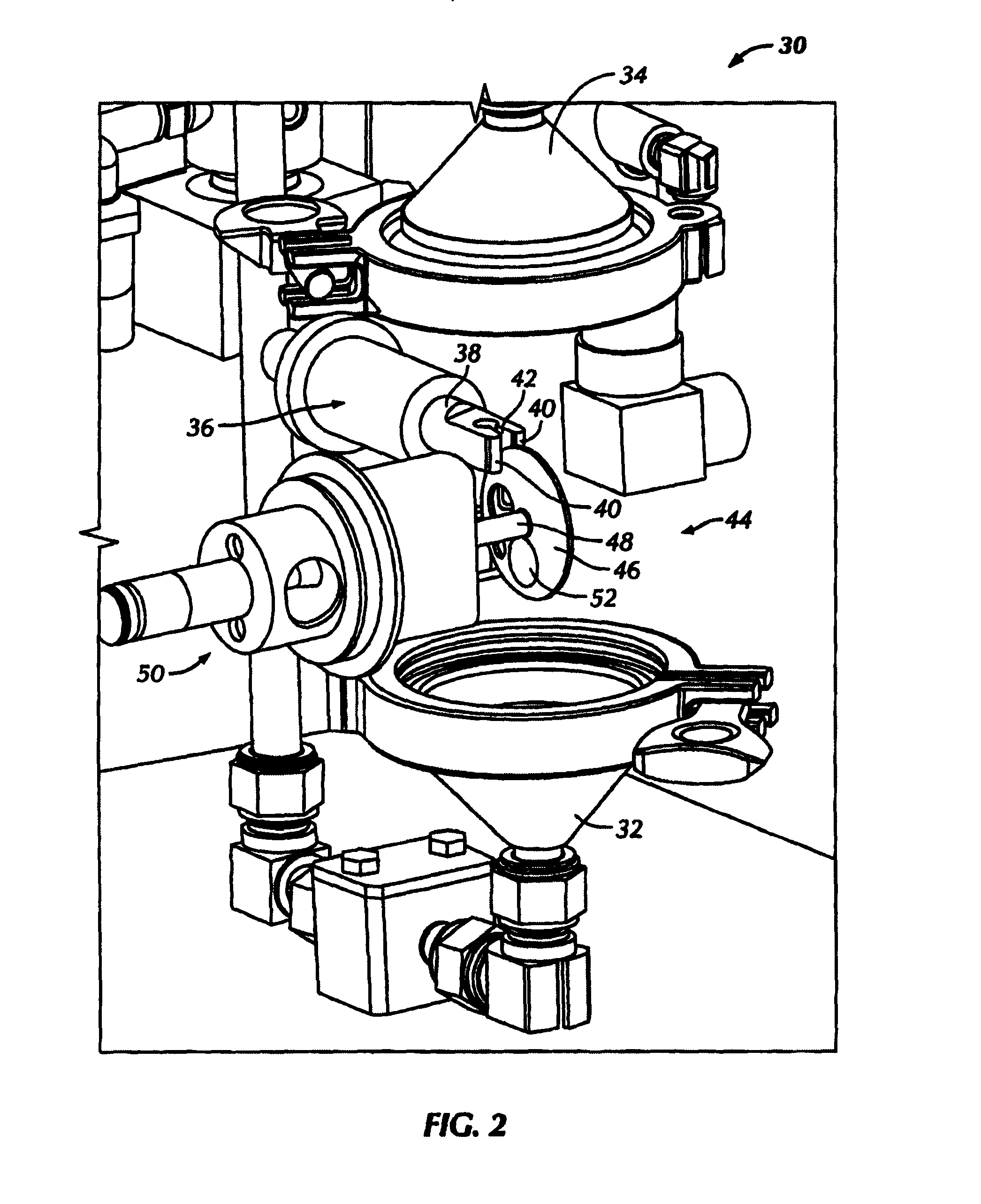
[0036]Referring to FIG. 1, a general schematic of an automated fluid property analyzer 10 in accordance with embodiments disclosed herein is shown. The automated fluid proper...


PUM

PropertyMeasurementUnit
viscosityaaaaaaaaaa
voltageaaaaaaaaaa
currentaaaaaaaaaa

Abstract

An automatic drilling fluid property analyzer including a housing having an inlet and an outlet; at least one valve disposed proximate the inlet and configured to open and close to provide a sample of fluid into the housing; an electronic control module configured to send a signal to the at least one valve; a probe assembly operatively coupled to the electronic control module, the probe assembly including an electrode probe having two electrodes and a probe gap therebetween; a viscometer sleeve disposed in the housing; a bob disposed in the sleeve, wherein an annulus is formed between the viscometer sleeve and the bob, and wherein at least one of the viscometer sleeve and the bob is configured to rotate, a motor operatively coupled to at least one of the viscometer sleeve and the bob; and a torque measuring device operatively coupled to the viscometer sleeve and the bob.

Description

BACKGROUND OF INVENTION[0001]1. Field of the Invention[0002]Embodiments disclosed herein relate to an automated meter to measure the electrical stability of drilling fluids. More specifically, embodiments disclosed herein relate to a drilling fluid analyzer for determining viscosity, gel strength, and or electric stability. More specifically still, embodiments disclosed herein relate to methods and systems for determining viscosity, gel strength, and or electric stability of drilling fluids that include automation and remote control.[0003]2. Background Art[0004]When drilling oil and / or gas wells, oil-based drilling fluids are often used to cool the drill bit, remove rock chips, and control subsurface fluids. Various properties of this fluid can be measured to compute useful results. For example, the electrical stability of drilling fluid is a property that is typically measured using an electrical stability (ES) test. The ES test is typically a manual test that is performed by a mud...

Claims


Application Information

Patent Timeline
Patent Type & Authority Applications(United States)
IPC IPC(8): G01N33/28G01N11/10G01N27/92G01N21/64E21B21/01E21B47/00
CPCG01N33/2823E21B21/01G01N11/10G01N27/92G01N21/64E21B47/00G01N11/14G01N23/223
Inventor STOCK, TORERONAES, EGILHILTON, THOMAS
Owner SHCLUMBERGER NORGE AS
Learn More