Self learning radio frequency monitoring system for identifying and locating faults in electrical distribution systems

a radio frequency monitoring and fault detection technology, applied in automated test systems, testing circuits, instruments, etc., can solve the problems of small electrical fault arcs that jump across cracks, rfm does not determine the location of equipment, rf emission activity, etc., and achieve the effect of high power plant reliability

Active Publication Date: 2015-11-05
SIEMENS ENERGY INC
View PDF0 Cites 21 Cited by
  • Summary
  • Abstract
  • Description
  • Claims
  • Application Information

AI Technical Summary

Benefits of technology

[0015]When utilizing the EFM system and method embodiments of the invention, faulty electrical equipment in the EDS, including the generator, can be repaired during a scheduled period of down time resulting in higher power plant reliability.

Problems solved by technology

One characteristic that can affect the field is cracking in the conductor causing small electrical fault arcs to jump across the crack.
Additionally variations in the field may also be caused by imperfections in the insulation that can allow partial electrical fault discharges consisting of very small mini-arcs on the surface of the insulation.
However, the RFM does not determine the location of the equipment that is causing the RF emission activity: only its existence.
The fault locating Utility customers find the process cumbersome and do not want the additional burden of finding the source of the problem.
Typical plant maintenance practice indicates that the source of such problems become known eventually, usually when the electrical equipment in the EDS fails.
Existing electrical fault detection systems and methods do not efficiently isolate location of RF emissions in power plant electrical distribution systems.
Those systems do not efficiently characterize whether an RF emission is an indicia of an existing or incipient electrical fault or whether the RF emission is merely part of an EDS operating state that does not negatively impact its safe operation (SO).

Method used


Image

  • Self learning radio frequency monitoring system for identifying and locating faults in electrical distribution systems
  • Self learning radio frequency monitoring system for identifying and locating faults in electrical distribution systems
  • Self learning radio frequency monitoring system for identifying and locating faults in electrical distribution systems

Examples


Embodiment Construction

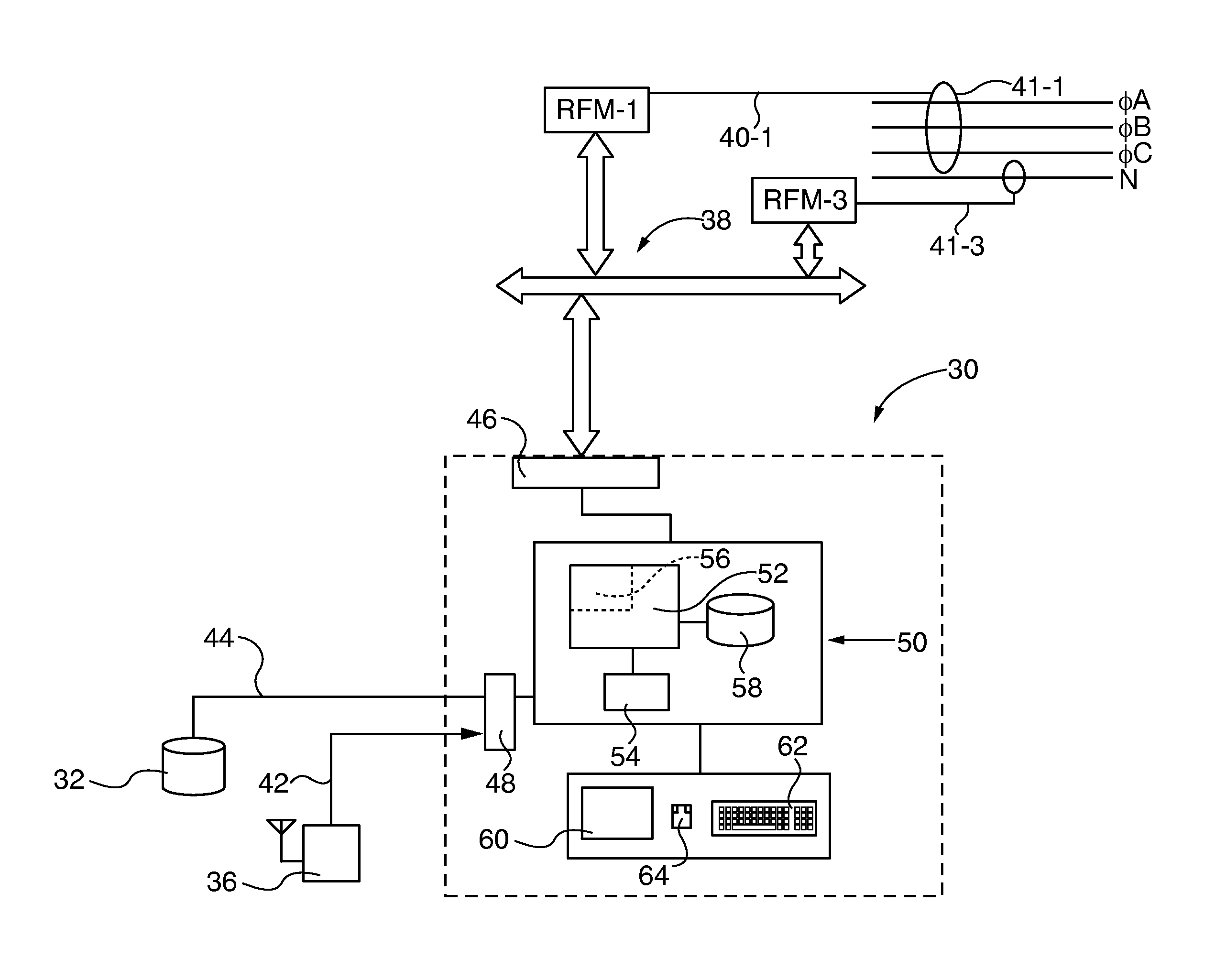
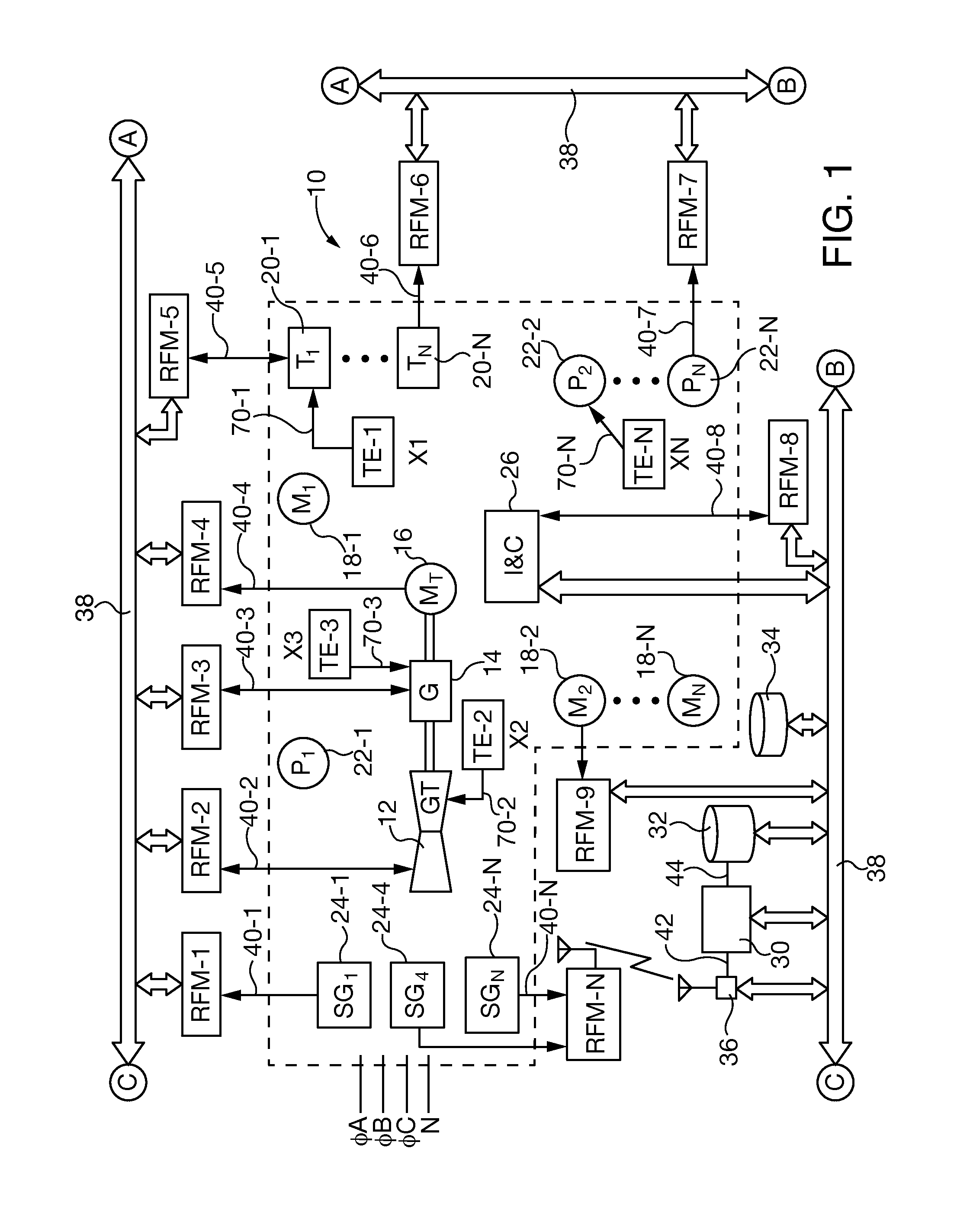
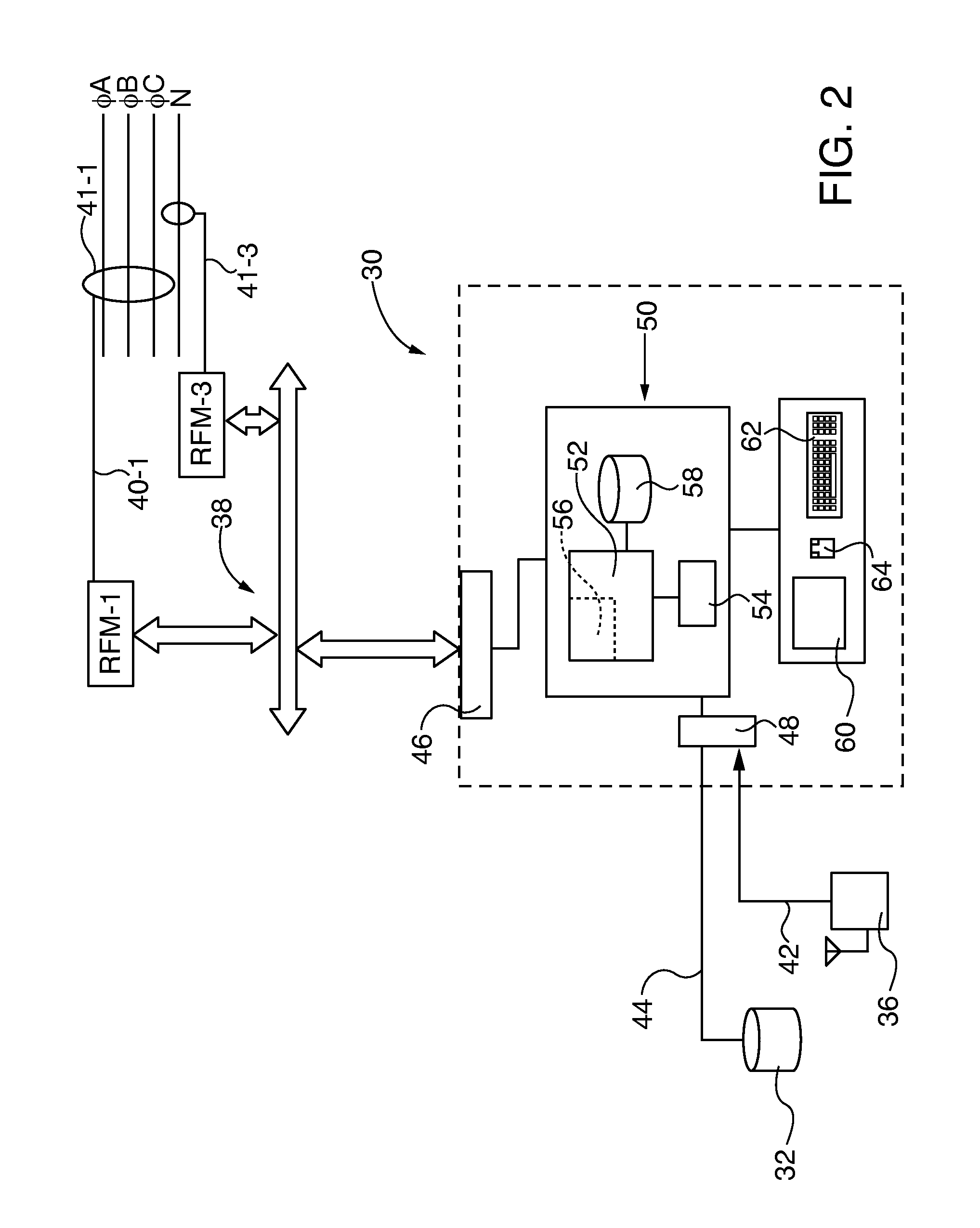
[0025]After considering the following description, those skilled in the art will realize that the by the teachings of the present invention electrical faults are detected in electrical distribution systems (EDS) by detection and location of radio frequency (RF) emissions generated by the fault with multiple time synchronized radio frequency monitors (RFM) distributed about the EDS. In embodiments of the invention the RFM location is reconfigurable to accommodate changes in the EDS configuration and / or component hardware. The RFMs are coupled to a self-learning, electrical fault monitor (EFM) that characterizes and / or locates electrical faults based on operating state (OS) patterns learned from transmission of test signals generated within the in the distributions system and / or that are preloaded into an EFM accessible base of stored knowledge. RF emissions data samples are characterized as safe operation (SO) states or potential electrical faults by accessing a base of stored knowle...


PUM


Abstract

Electrical faults are detected in electrical distribution systems (EDS) by detection and location of radio frequency (RF) emissions generated by the fault with multiple time-synchronized radio frequency monitors (RFM) distributed about the EDS. The RFMs are coupled to a self-learning, electrical fault monitor (EFM) that characterizes and/or locates electrical faults based on operating state (OS) patterns learned from transmission of test signals generated within the EDS. RF emissions data samples are characterized as safe operation (SO) states or potential electrical faults by accessing a base of stored knowledge concerning fault emission characteristics and/or synchronized time of arrival at each RFM. Information in the base of stored knowledge is updated to include new EDS operating states (OS). Confidence level associations, location of new radio frequency emission patterns and whether those patterns are indicative of safe operating (SO) conditions or electrical faults are stored in the base of stored knowledge.

Description

BACKGROUND OF THE INVENTION[0001]1. Field of the Invention[0002]The invention relates to electrical fault detection in electrical distribution systems (EDS) by detection and location of radio frequency (RF) emissions generated by the fault. More particularly the invention relates to self-learning radio frequency electrical fault monitor (EFM) systems and methods, having time synchronized distributed radio frequency monitors, wherein the monitoring system is trained to characterize and / or locate electrical faults based on operating state (OS) patterns learned from transmission of test signals generated within the distributions system. During operation, radio frequency emissions from the EDS are evaluated by multiple radio frequency monitors (RFM) as safe operation (SO) or potential electrical faults by accessing a base of stored knowledge concerning fault emission characteristics and / or synchronized time of arrival at each monitor. During evaluation the EFM system establishes one or ...

Claims


Application Information

Patent Timeline
Patent Type & Authority Applications(United States)
IPC IPC(8): G01R31/28G01R17/02
CPCG01R17/02G01R31/2834G01R31/085G01R31/14
Inventor OAK, JON PATRICKTHOMPSON, EDWARD DAVID
Owner SIEMENS ENERGY INC
Why Eureka
Try Eureka