
Systems and methods for suppressing rush current noise in a power switch cell

a technology of rush current noise and power switch cell, which is applied in the direction of emergency protective arrangements for limiting excess voltage/current, electrical equipment, and arrangements responsive to excess current, etc., can solve the problems of large power/ground bounce and the technique requires relatively complex control and timing capabilities

Inactive Publication Date: 2015-11-05
QUALCOMM INC
View PDF2 Cites 0 Cited by
  • Summary
  • Abstract
  • Description
  • Claims
  • Application Information

AI Technical Summary

Benefits of technology

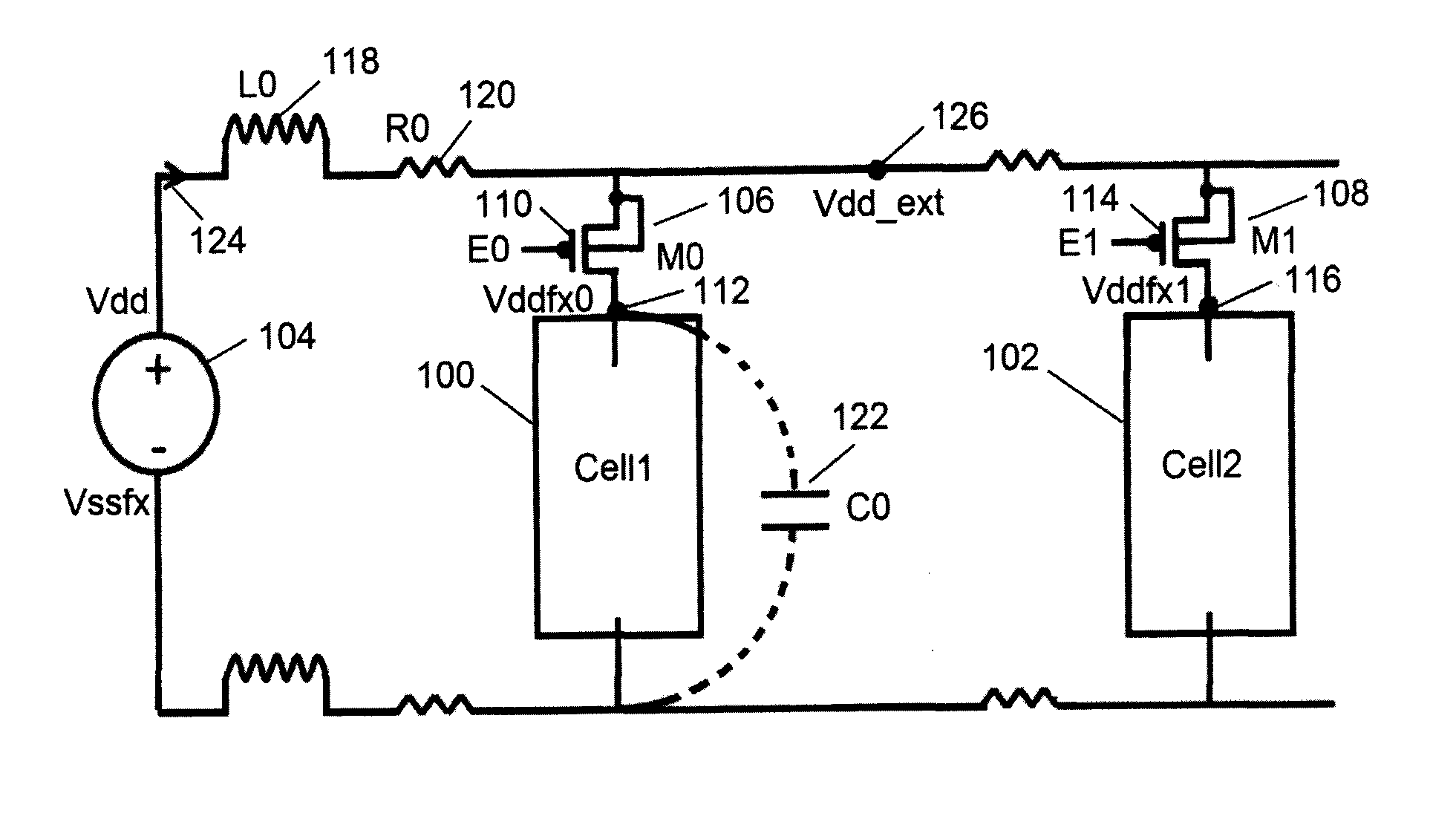
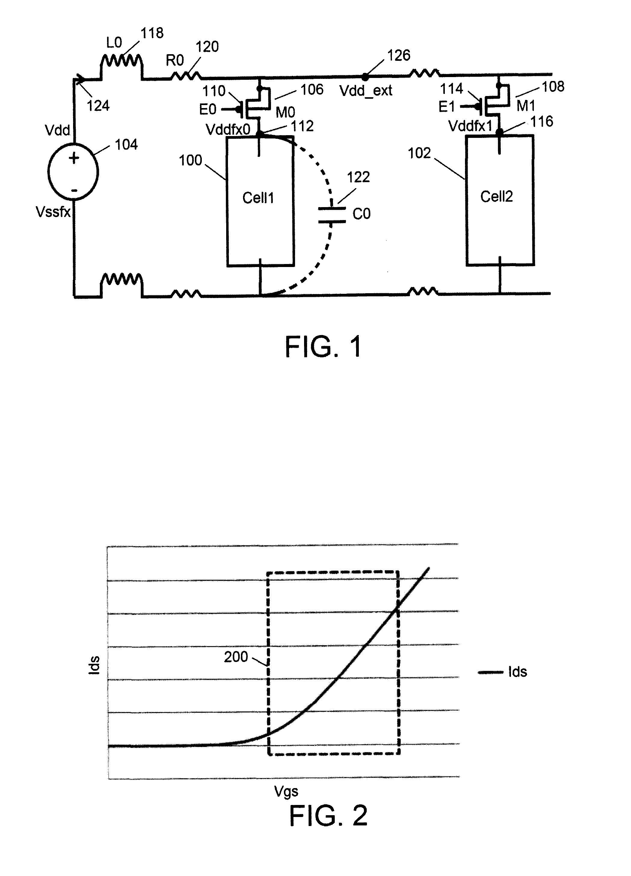
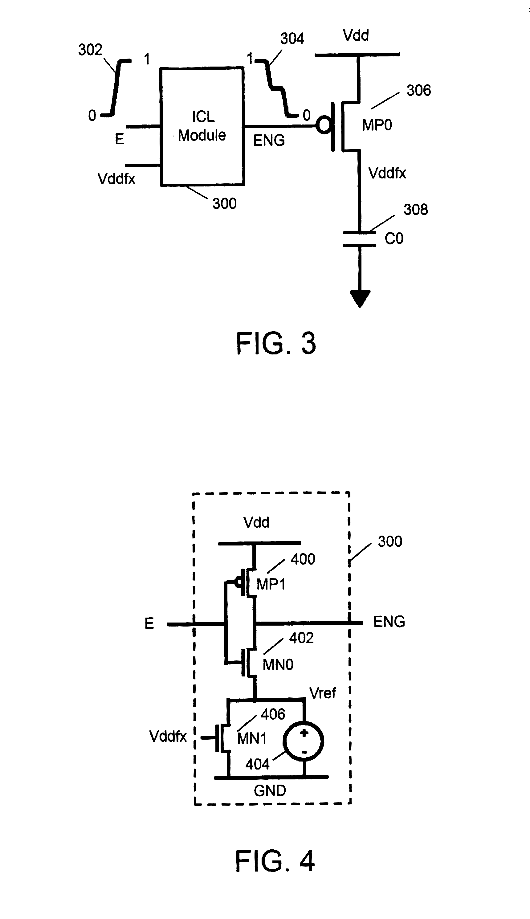
This patent describes a system for controlling the power supply to a circuit, which includes a power switch that can transition between low conductance, moderate conductance, and high conductance states based on a control signal. An inrush current limiter module is used to control the transition of the control signal between different levels, and can output multiple intermediate levels between the first and second values. The inrush current limiter module can also be controlled by feedback from the power switch. The power switch can be a MOSFET or a CMOS inverter. The system can be used to control the power supply to a cell of a circuit, and can provide a smooth transition between different levels of power.

Problems solved by technology

Although power switch cells provide an effective mechanism for managing power consumption, their use may involve side effects that should be addressed.
This in-rush current may induce a power / ground bounce large enough to disturb the state of neighboring active circuits.
As will be appreciated, these techniques require relatively complex control and timing capabilities.

Method used


Image

  • Systems and methods for suppressing rush current noise in a power switch cell
  • Systems and methods for suppressing rush current noise in a power switch cell
  • Systems and methods for suppressing rush current noise in a power switch cell

Examples


Embodiment Construction

[0024]At the outset, it is to be understood that this disclosure is not limited to particularly exemplified materials, architectures, routines, methods or structures as such may, of course, vary. Thus, although a number of such options, similar or equivalent to those described herein, can be used in the practice or embodiments of this disclosure, the preferred materials and methods are described herein.

[0025]It is also to be understood that the terminology used herein is for the purpose of describing particular embodiments of this disclosure only and is not intended to be limiting.

[0026]The detailed description set forth below in connection with the appended drawings is intended as a description of exemplary embodiments of the present invention and is not intended to represent the only exemplary embodiments in which the present invention can be practiced. The term “exemplary” used throughout this description means “serving as an example, instance, or illustration,” and should not ne...


PUM


Abstract

A System and a method are disclosed for suppressing rush current noise in a power switch cell. The system comprises: a power switch (306) having an operational condition dependent upon the state of a control signal; and an inrush current limiter module (300) for outputting the control signal. The control signal transitions from a first value to an intermediate value and from the intermediate value to a second value, wherein the power switch is configured to operate in a low conductive (OFF) condition when the control signal has the first value, to operate in a high conductive (ON) condition when the control signal has the second value, and to operate in a moderately conductive condition when the control signal has the intermediate value. Therefore, when the power switch transitions from the OFF condition to the ON condition, the rush current noise may be reduced.

Description

FIELD OF THE PRESENT INVENTION[0001]This disclosure generally relates to power switch cells and more specifically to header or footer switches having reduced rush current noise.BACKGROUND OF THE INVENTION[0002]To increase efficiency, power gating techniques have been developed to selectively supply power to one or more subsets of circuitry, allowing them to be depowered at times their function is not required. As such, areas of a circuit, known as cells, may be controlled by a power switch. Thus, the use of power switch cells may reduce the current consumed by the circuit when in an OFF condition, which is a desirable attribute for modern integrated circuits. The switches are typically operated by signals generated by a control logic block that determines when the cells may be disabled to reduce power use. Generally, a metal oxide semiconductor field effect transistor (MOSFET) may be a P-type (PMOS) or an N-type (NMOS). A PMOS may be used as the switch for the cell as a header switc...

Claims


Application Information

Patent Timeline
Patent Type & Authority Applications(United States)
IPC IPC(8): H02H9/02
CPCH02H9/02H02H9/001
Inventor CAI, YANFEICHEN, GUANG XIAOHUANG, SHANGQU
Owner QUALCOMM INC
Learn More