
Brush Plate

Active Publication Date: 2015-11-05
JOHNSON ELECTRIC INTERNATIONAL AG
View PDF12 Cites 0 Cited by
  • Summary
  • Abstract
  • Description
  • Claims
  • Application Information

AI Technical Summary

Benefits of technology

The patent text describes a brush plate design for motors that includes conductors and overheat protection portions. The design features resilient latches that keep the conductor secure in place, and the overheat protection portions are flexible and can be placed at any location on the conductor. The U-shaped, Z-shaped, or M-shaped bend structure of the overheat protection portions increases their anti-shock capability and helps to quickly absorb heat. The design also allows for adjustability of the overheat protection portion based on the specific operating temperature requirements of the motor. Overall, this design simplifies motor design and improves motor safety.

Problems solved by technology

When the current is overly large, or the heat inside the motor is too high, the solder of the solder joint melts, which allows the resilient strip to pop up thus breaking the circuit.
However, in this type of overheat protection device, the solder joint has a poor reliability.
The solder may release the strip due to shock or corrosion during use, which would cause the motor to malfunction.
In addition, the various solder materials used have a narrow melting range, which results in such devices only being suitable for a limited range of operating conditions.

Method used


Image

  • Brush Plate
  • Brush Plate
  • Brush Plate

Examples


Embodiment Construction

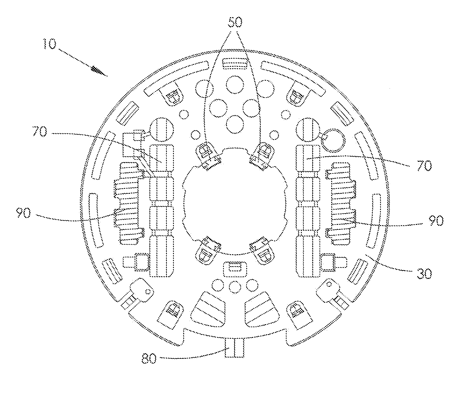
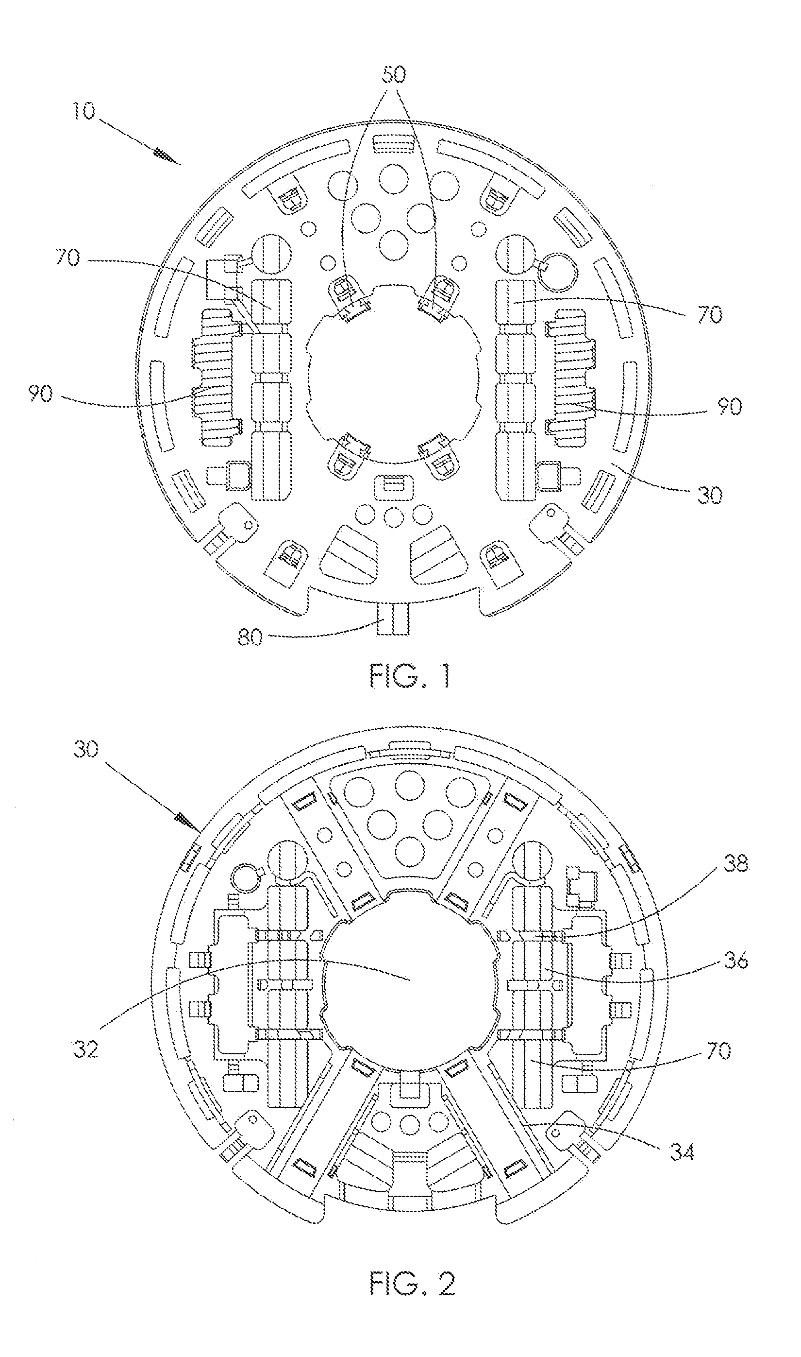
[0025]FIG. 1 is a plan view of a brush plate according to one embodiment of the present invention. FIG. 2 is a view of the other side of the brush plate of FIG. 1, with various components removed such as brushes, inductors and power leads.

[0026]The brush plate 10 can be used to supply power to the rotor of a brush motor. The brush plate includes an insulating substrate 30, a plurality of brushes 50 mounted on the insulating substrate 30, and a plurality of conductors 70 fixed to the insulating substrate 30 for supplying power to the brushes 50.

[0027]The insulating substrate 30 has a generally circular shape. Depending on the shape of a motor end cover, the insulating substrate 30 may also have another shape such as square shape. The insulating substrate 30 defines a central through hole 32 for allowing insertion of a commutator of the motor. Segments of the commutator are electrically connected with windings of the rotor. A plurality of brush holders 34 is disposed around the throug...


PUM


Abstract

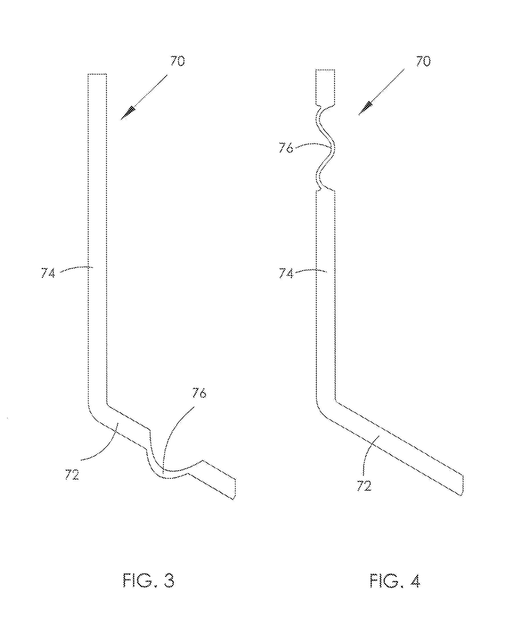
A brush plate has an insulating substrate, at least one pair of brushes mounted on the insulating substrate, and a conductor for supplying power to the brushes. The conductor includes at least one overheat protection portion having a smaller cross sectional area than adjacent portions of the conductor. By integrally forming the overheat protection portions on the conductors, no extra overheat protection device is required. Preferably, the overheat protection portion has a bent structure. The bent structure may be U-shape, Z-shape, M-shape or wave-shape. The bent structure can increase the anti-shock capability of the conductor and shorten the response time of the overheat protection portion.

Description

CROSS REFERENCE TO RELATED APPLICATIONS[0001]This non-provisional patent application claims priority under 35 U.S.C. §119(a) from Patent Application No. 201410188780.7 filed in The People's Republic of China on May 5, 2014, the entire contents of which are hereby incorporated by reference.FIELD OF THE INVENTION[0002]This invention relates to a brush plate and in particular, to a brush plate with overheat protection for a brush motor.BACKGROUND OF THE INVENTION[0003]A brush plate of a brush motor typically includes brushes, a plurality of other electrical components, and conductors for supplying power to the brushes and electrical components. Overheat protection devices may be connected between the conductors and the brushes, or between the conductors and other electrical components to prevent overly large currents from flowing through the motor which would damage the motor. In a typical example of such a brush plate, the overheat protection device includes a resilient strip as shown...

Claims


Application Information

Patent Timeline
IPC IPC(8): H02K13/00H02K11/02H01R39/36
CPCH02K13/00H02K11/02H01R39/36H02K5/148H02K11/27
Inventor CHUNG, MING YAU
Owner JOHNSON ELECTRIC INTERNATIONAL AG
Learn More