
Multi-layer virtual infrastructure embedding in software-defined flexible-grid transport networks

a flexible, network technology, applied in data switching networks, digital transmission, wavelength-division multiplex systems, etc., to achieve the effect of maximizing the use of existing optical channels, minimizing the switching of virtual links, and maximizing spectral efficiency

Active Publication Date: 2015-11-05
NEC CORP
View PDF3 Cites 2 Cited by
  • Summary
  • Abstract
  • Description
  • Claims
  • Application Information

AI Technical Summary

Benefits of technology

The patent describes a method and system for embedding virtual infrastructure demands in a software-defined network. The system constructs an auxiliary graph with virtual links between physical nodes and maps virtual links over physical links to maximize use of existing optical channels and minimize switching of virtual links. The system also determines a set of potential solutions for embedding the virtual infrastructure demands and selects a solution that maximizes the weighted average of spectrum needed to support the demands and the cost of provisioning them. The technical effect of the patent is to improve the efficiency and cost-effectiveness of embedding virtual infrastructure demands in a software-defined network.

Problems solved by technology

In software-defined flexible-grid transport networks, an open control plane challenge is how to map Virtual network Infrastructure (VI) demands over multi-layers of physical substrates.
The problem is how to map VNs over Physical Nodes (PNs), how to map VLs over transport connections, how to route transport connections over Physical Links (PLs), and how to assign spectral resources to the transport connections.

Method used


Image

  • Multi-layer virtual infrastructure embedding in software-defined flexible-grid transport networks
  • Multi-layer virtual infrastructure embedding in software-defined flexible-grid transport networks
  • Multi-layer virtual infrastructure embedding in software-defined flexible-grid transport networks

Examples


Embodiment Construction

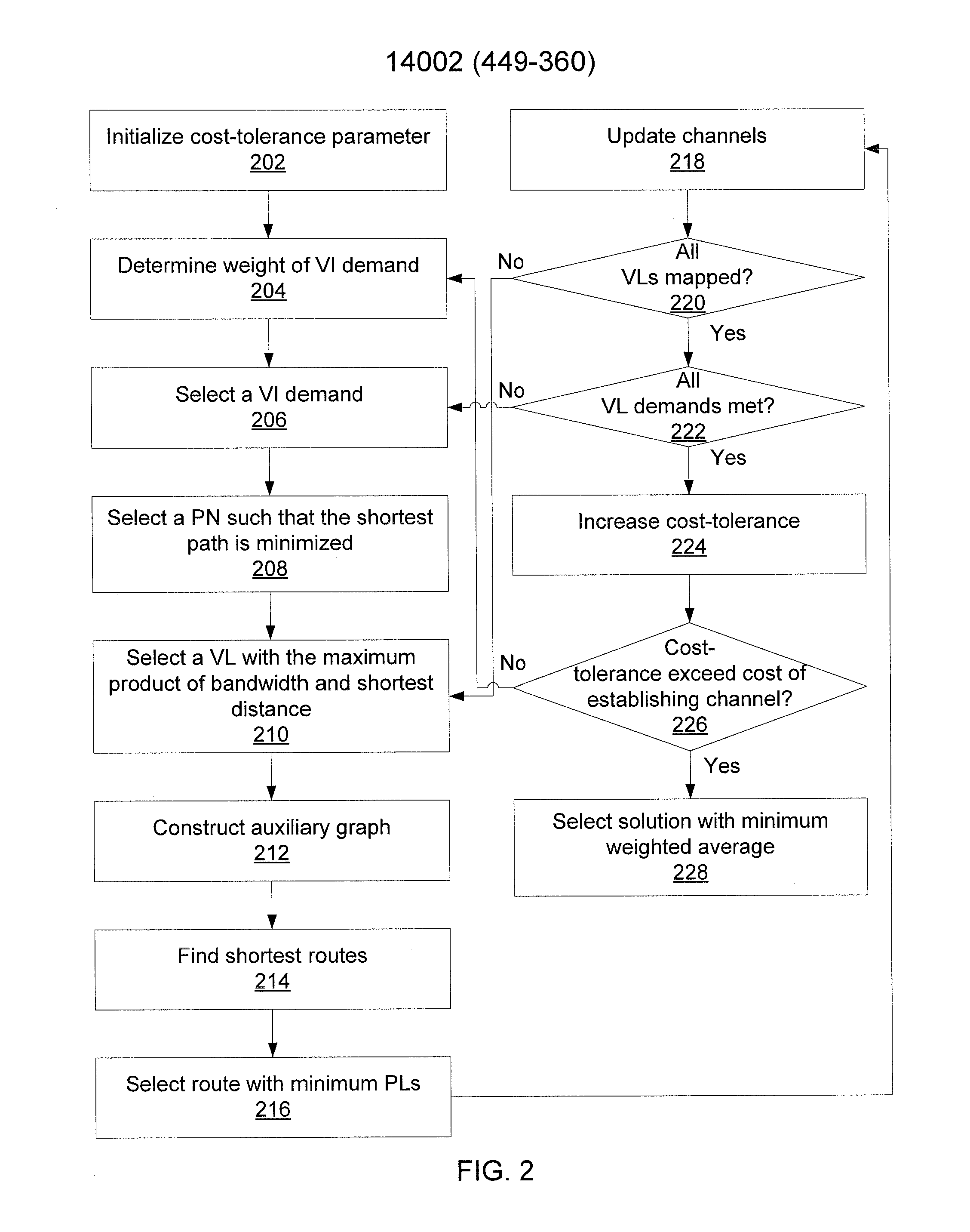
[0010]Embodiments of the present invention perform multi-layer virtual infrastructure (VI) embedding over software-defined flexible grid transport networks. This is accomplished while minimizing the spectrum needed to embed VI demands while maximizing the revenue of providing virtualization services over a physical infrastructure. The present embodiments employ auxiliary graphs that efficiently provision VI demands in the minimum amount of spectrum while allowing a certain amount of cost for the mapping of a virtual link (VL). The present embodiments iterate over different cost thresholds to find a set of potential solutions. Then a solution is selected that minimizes a weighted average of needed spectrum and cost of mapping the VI demands.

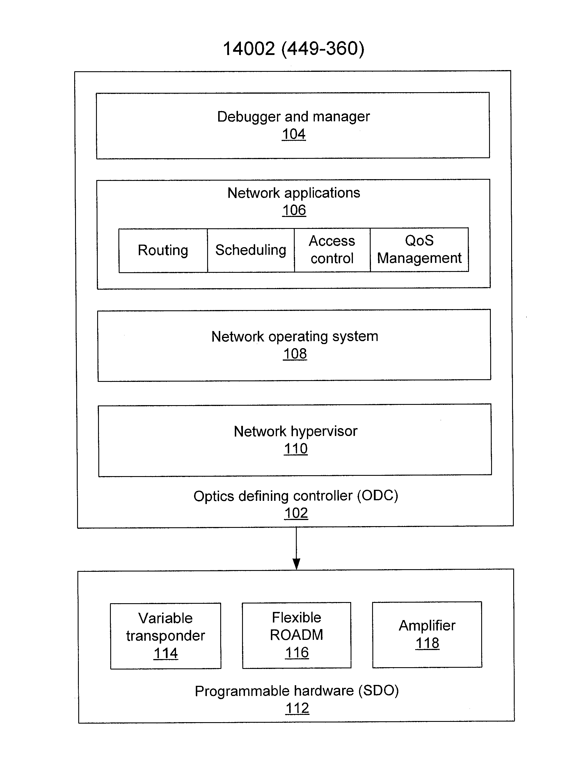
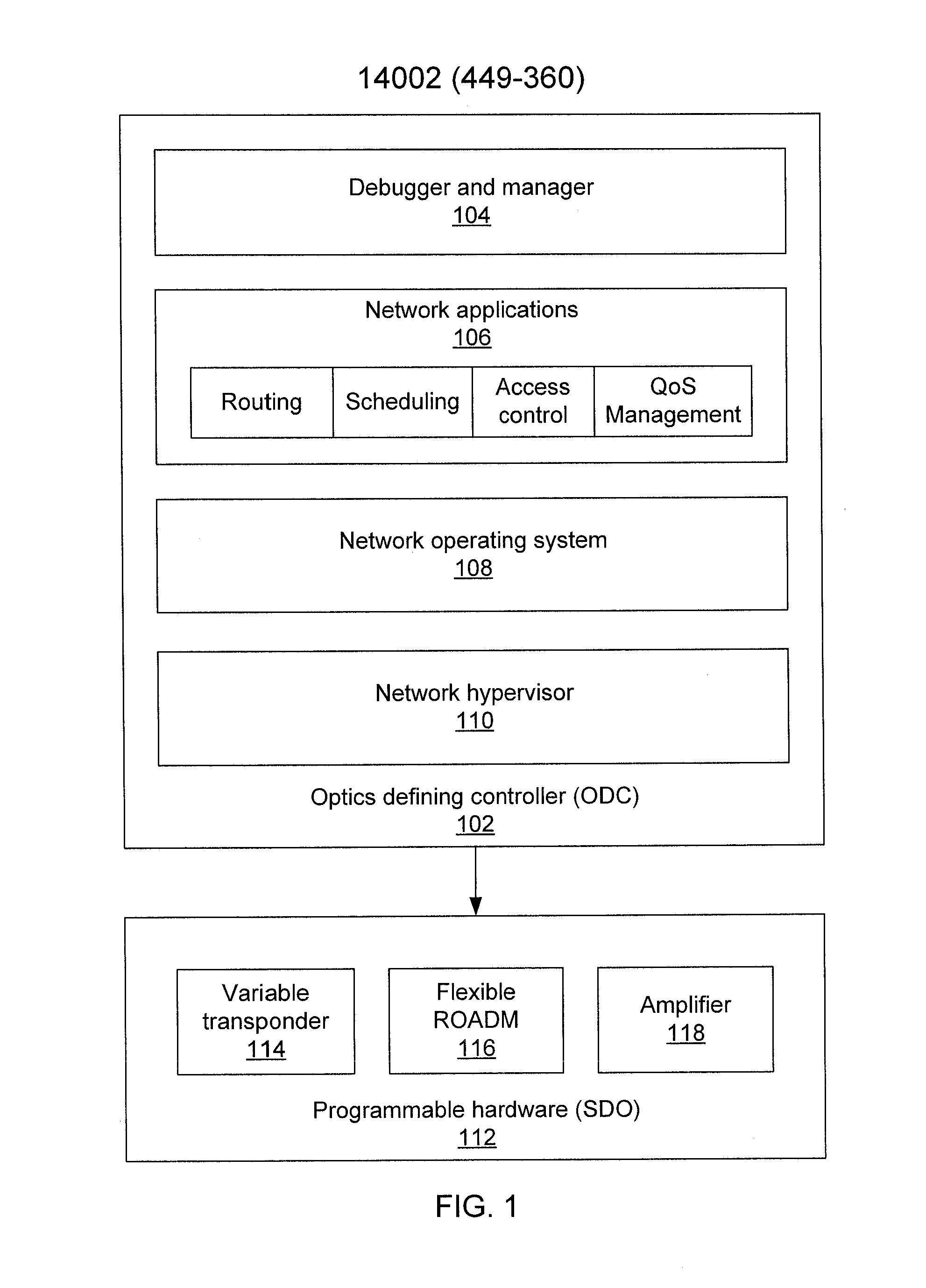
[0011]Referring now to FIG. 1, the architecture of an optical transport software defined network (SDN) is shown. The control plane, implemented by an optics defining controller (ODC) 102, is abstracted from physical hardware of the networking elem...


PUM


Abstract

Methods and systems for embedding VI demands in a software-defined network include mapping virtual nodes over physical nodes in a network topology. An auxiliary graph including virtual links between physical nodes that have a residual capacity sufficient to meet a virtual infrastructure demand is constructed. Virtual links over physical links are mapped to maximize use of existing optical channels and to minimize switching of a virtual link between a wavelength division multiplexing layer and an IP layer. New optical channels with a maximum spectral efficiency are established. A set of potential solutions for embedding a set of virtual infrastructure demands is determined. A solution is selected from the set of potential solutions that maximizes a weighted average of spectrum needed to support the set of virtual infrastructure demands and a cost of provisioning the virtual infrastructure demands.

Description

RELATED APPLICATION INFORMATION[0001]This application claims priority to provisional application No. 61 / 987,856, filed May 2, 2014, the contents thereof being incorporated herein by reference.BACKGROUND OF THE INVENTION[0002]Software-defined network (SDN) architecture enables network programmability to support multi-vendor, multi-technology, multi-layer communications and offers network infrastructure as a service. Efforts to integrate optical transport within IP / Ethernet based SDN architectures are ongoing with the goal of leveraging optical transmission benefits, such as low interference, long reach, and high capacity transmission with lower power consumption. Such a network is known as a transport SDN.[0003]Transport SDNs are implemented by enabling flexibility and programmability in wavelength division multiplexing (WDM) transmission and switching network elements, such as transponders and reconfigurable optical add-drop multiplexers (ROADMs), management of optical channels such...

Claims


Application Information

Patent Timeline
Patent Type & Authority Applications(United States)
IPC IPC(8): H04L12/24H04J14/02
CPCH04L41/22H04J14/0227H04L41/12H04J14/0257H04J14/0271H04L41/122
Inventor PATEL, ANKITKUMARJI, PHILIP NANWANG, TING
Owner NEC CORP
Learn More