Systems, methods, apparatuses, and computer-readable storage media for collecting color information about an object undergoing a 3D scan

a technology of color information and object, applied in the field of collecting color information about objects undergoing a three-dimensional (3d) scan, can solve the problems of difficult to distinguish between clinically relevant areas (e.g., teeth) and unnecessary areas (e.g., tongue and cheek), and achieve the effect of facilitating the optimal preparation and placement of a dental crown and facilitating the scanning process

Active Publication Date: 2015-11-05
DENTSPLY SIRONA INC
View PDF4 Cites 17 Cited by
  • Summary
  • Abstract
  • Description
  • Claims
  • Application Information

AI Technical Summary

Benefits of technology

[0015]The method can be useful for displaying precise, color 3D model of the inside of a patient's mouth and assisting dental professionals in identifying clinically relevant areas. For example, the method can assist a dental professional to identify a margin between a ground-down portion of a toot

Problems solved by technology

When performing a 3D scan inside a patient's mouth with a camera, it can be difficult to orient the camera correctly to scan the anatom

Method used


Image

  • Systems, methods, apparatuses, and computer-readable storage media for collecting color information about an object undergoing a 3D scan
  • Systems, methods, apparatuses, and computer-readable storage media for collecting color information about an object undergoing a 3D scan
  • Systems, methods, apparatuses, and computer-readable storage media for collecting color information about an object undergoing a 3D scan

Examples


Embodiment Construction

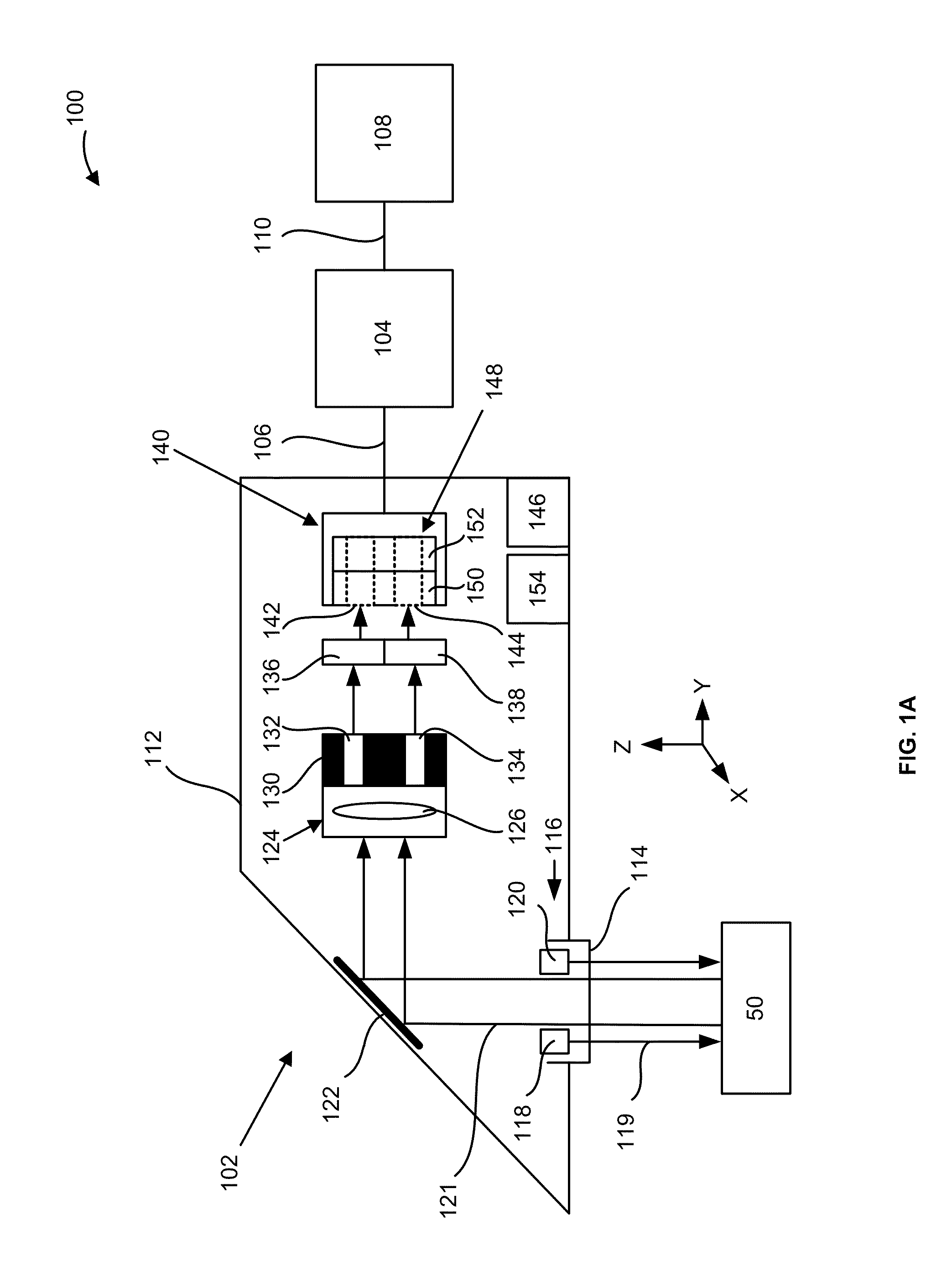
[0033]FIG. 1A illustrates a block diagram of a 3D scanning system 100 that collects color information from an object 50 undergoing a 3D scan and displays a 3D color representation of the object 50. The 3D scanning system 100 includes a handpiece 102, a computer system 104 connected to the handpiece using a cable 106, and a display unit 108 connected to the computer system 104 using a cable 110.

[0034]The handpiece 102 includes a housing 112 that has a window 114 in a lower surface thereof. The handpiece 102 also includes an illumination unit 116 that projects light 119 onto the object 50 through the window 114. According to an example embodiment herein, the illumination unit 116 includes light emitting diodes (LEDs), for example, LEDs 118 and 120, that project white light as light 119 onto the object 50. In another example embodiment herein, the illumination unit 116 includes a plurality of white light projecting LEDs, the plurality numbering, for example, twelve such LEDs (not shown...


PUM


Abstract

A method of performing a three-dimensional (3D) scan of an object includes applying an optical contrast powder to the object and illuminating the object with light. First and second two-dimensional (2D) color image data corresponding to the object is generated. First and second 2D monochrome image data corresponding to the object is generated using the first and second 2D color image data. 3D data corresponding to the object is generated using the first and second monochrome 2D image data. Color 3D image data corresponding to the object is generated by adding color information to the 3D data. The color 3D image data is displayed.

Description

BACKGROUND[0001]1. Field[0002]The present disclosure relates to collecting color information about an object undergoing a three-dimensional (3D) scan, and, more particularly, to generating and displaying 3D color image data corresponding to one or more objects, for example, one or more teeth.[0003]2. Description of Related Art[0004]Computer-Aided Design (CAD) and Computer-Aided Manufacturing (CAM) techniques have been used to create digital models of the interiors of patients' mouths. The digital models have been used to design and manufacture prosthetic dental items such as inlays, onlays, bridges, crowns, and veneers. Conventional systems used to scan the interiors of patients' mouths to produce such digital models generate and display 3D monochrome data. When performing a 3D scan inside a patient's mouth with a camera, it can be difficult to orient the camera correctly to scan the anatomy of interest and to distinguish between clinically relevant areas (e.g., the teeth) and unnec...

Claims


Application Information

Patent Timeline
IPC IPC(8): H04N1/00H04N1/46
CPCH04N1/465H04N1/00827A61C9/0053H04N1/19594H04N13/254H04N13/207G01B11/2513A61C9/006H01L27/146
Inventor PFEIFFER, JOACHIMLU, JIANHARVARD, ALEXEIVOSS, BJOERNFRANK, THIEL
Owner DENTSPLY SIRONA INC
Why Eureka
Try Eureka