Methods and apparatus for imaging in scattering environments

a scattering environment and imaging method technology, applied in the field of methods and apparatus for imaging in scattering environments, can solve the problems of limited success, high cost, complex and/or complex imaging techniques through scattering media in either air or water, and conventional systems do not provide color images of objects, etc., and achieve the effect of limited success

Active Publication Date: 2015-11-05
RAYTHEON CO
View PDF7 Cites 31 Cited by
  • Summary
  • Abstract
  • Description
  • Claims
  • Application Information

AI Technical Summary

Benefits of technology

[0002]As discussed above, conventional technologies for imaging through scattering media in either air or water are expensive and/or complex and have limited success. Additionally, conventional systems do not ...

Problems solved by technology

As discussed above, conventional technologies for imaging through scattering media in either air or water are expen...

Method used


Image

  • Methods and apparatus for imaging in scattering environments
  • Methods and apparatus for imaging in scattering environments
  • Methods and apparatus for imaging in scattering environments

Examples


Embodiment Construction

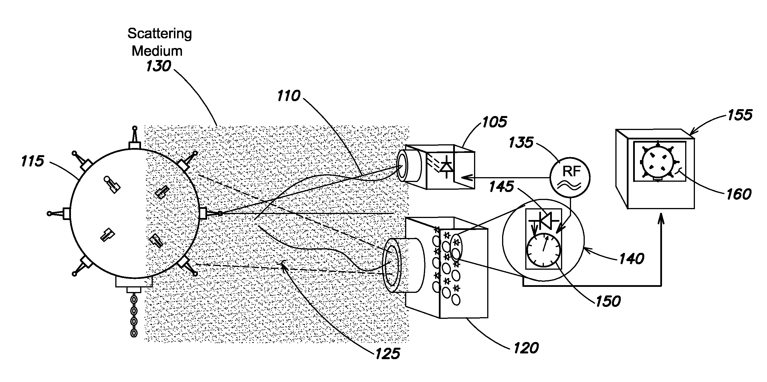
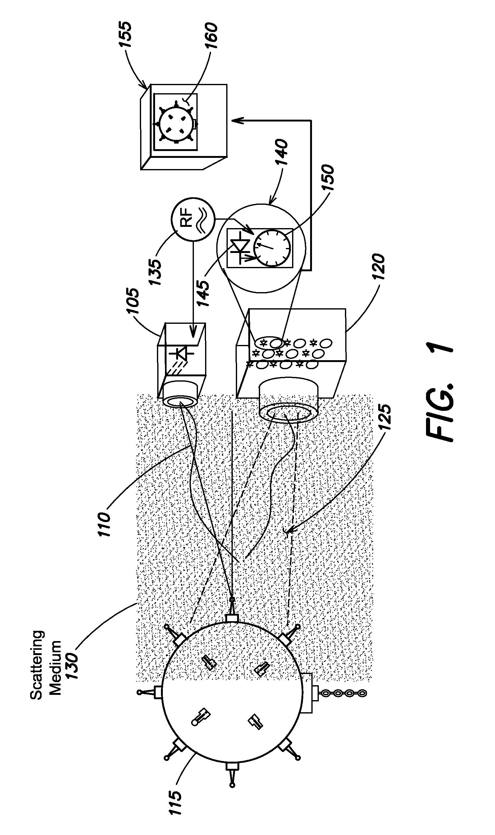
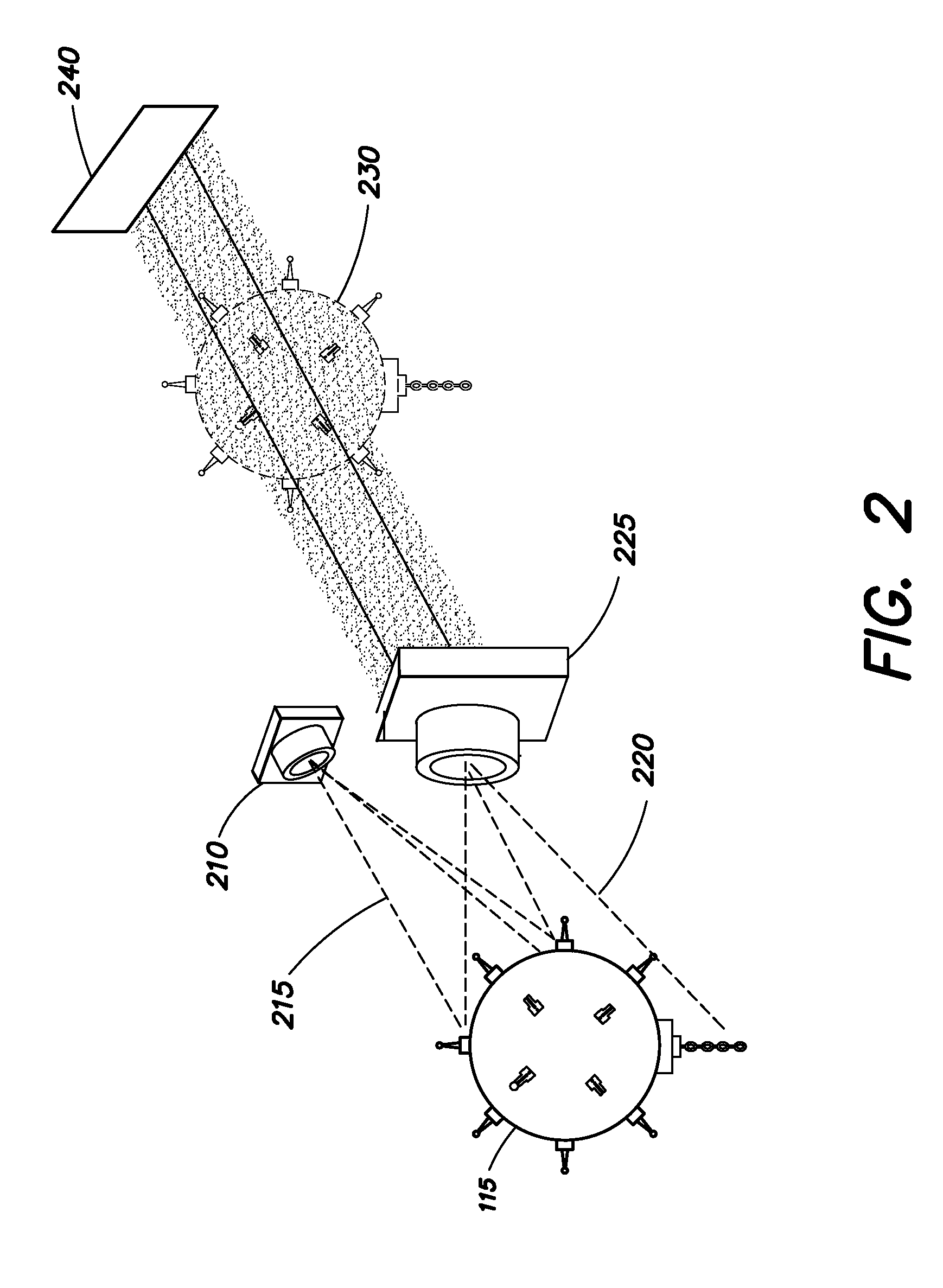
[0013]Near-object underwater inspection is an area of increasing interest for several applications, including in mine clearance with unmanned underwater vehicles (UUV). These and other underwater imaging systems typically include a single visible-spectrum optical sensor. As discussed above, one challenge to the successful use of these optical sensors results from the turbidity or cloudiness of the water. General sources of turbidity generally include small particulates, microscopic marine fauna and flora and other suspended particles in the water column. Light that is scattered from the entire volume of water (referred to herein as “out-of-plane scatter”) creates poor signal-to-noise ratio (S / N) optical images, or requires that the sensor be proximal to the object being inspected. These are challenges to both qualitative and quantitative analysis and characterization of underwater objects.

[0014]Accordingly, aspects and embodiments are directed to systems and methods for imaging obje...


PUM


Abstract

Systems and method for imaging through scattering media. One example of an imaging system includes an illuminator configured to produce a structured illumination pattern and to direct the structured illumination pattern into an imaging field through a scattering medium, a camera configured to receive reflections of the structured illumination pattern from an object in the imaging field and to provide corresponding image data, a master oscillator coupled to the illuminator and to the camera and configured to modulate the structured illumination pattern and to clock the camera so as to time gate the reflections of the structured illumination pattern and provide signal timing data, and a processor coupled to the camera and received to receive and process the image data and the signal timing data to produce an image of the object.

Description

BACKGROUND[0001]Optical imaging through turbid (e.g., cloudy) water results in poor signal-to-noise ratio data, compromising qualitative and quantitative analyses or requiring unacceptable operational constraints. Current solutions are technically complex and expensive, limiting their ability to be used in emerging low cost architectures. For example, certain conventional systems use Light Distancing and Ranging (LIDAR) which excludes out-of-object-plane light using time gating. However, such systems are generally large and expensive, and do not provide color-corrected images. Other approaches involve placing the optical sensor close to the object being imaged, which reduces the impact of scattering exponentially. However, for many applications requiring close-range imaging is undesirable and potentially risky. Some approaches focus on image processing to “clean up” images with scattering effects, but have limited ability to improve image quality. Photonic mixing devices (PMDs) also...

Claims


Application Information

Patent Timeline
IPC IPC(8): H04N5/225H04N9/64H04N9/04G01S17/18G01S17/894
CPCH04N5/2256H04N9/64H04N9/04G01S17/46G01B11/25G01S17/18G01S17/894H04N23/56H04N23/10
Inventor COTTRELL, WILLIAM
Owner RAYTHEON CO
Why Eureka
Try Eureka