Method of infrared image processing for non-uniformity correction

a non-uniformity correction and infrared image technology, applied in the field of infrared image sensors, can solve the problems of inability to use a shutter, increased weight and cost, and inability to meet the requirements of the measurement,

Active Publication Date: 2015-11-05
LYNRED
View PDF4 Cites 32 Cited by
  • Summary
  • Abstract
  • Description
  • Claims
  • Application Information

AI Technical Summary

Benefits of technology

[0018]According to one embodiment, determining the first scale factor comprises: applying a high-pass filter along the rows of the image; applying the high-pass filter to the column vector; and determining column averages of the filtered image, the first scale factor being determined based on a minimization of the differences between the column averages of the filtered image and the filtered values of the column vector.
[0021]According to one embodiment, determining the second scale factor comprises: determining, for each pixel of the input image and for each element of the dispersion matrix, a gradient value based on at least one adjacent pixel, the second scale factor being determined based on a minimization of the difference between the gradients of the input image and the gradients of the dispersion matrix.

Problems solved by technology

In the field of infrared (IR) imaging, performing offset correction in captured images, without the use of a shutter or shutter-like hardware, presents a major challenge for uncooled IR imaging devices, such as microbolometers, and also for cooled IR imaging devices.
This problematic is generally dealt with using an internal mechanical shutter in the imaging device, and involves periodically capturing an image while the shutter is closed in order to obtain a reference image of a relatively uniform scene that can then be used for calibration.
However, there are several drawbacks of using a shutter, such as the additional weight and cost, and the fragility of this component.
Furthermore, for certain applications, the use of a shutter is unacceptable due to the time that is lost while the shutter is closed and calibration takes place.
However, existing techniques are complex and / or do not adequately correct the image.

Method used


Image

  • Method of infrared image processing for non-uniformity correction
  • Method of infrared image processing for non-uniformity correction
  • Method of infrared image processing for non-uniformity correction

Examples


Embodiment Construction

[0037]While some of the embodiments in the following description are described in relation to a pixel array of the microbolometer type, it will be apparent to those skilled in the art that the methods described herein could be equally applied to other types of IR imaging devices, including cooled devices.

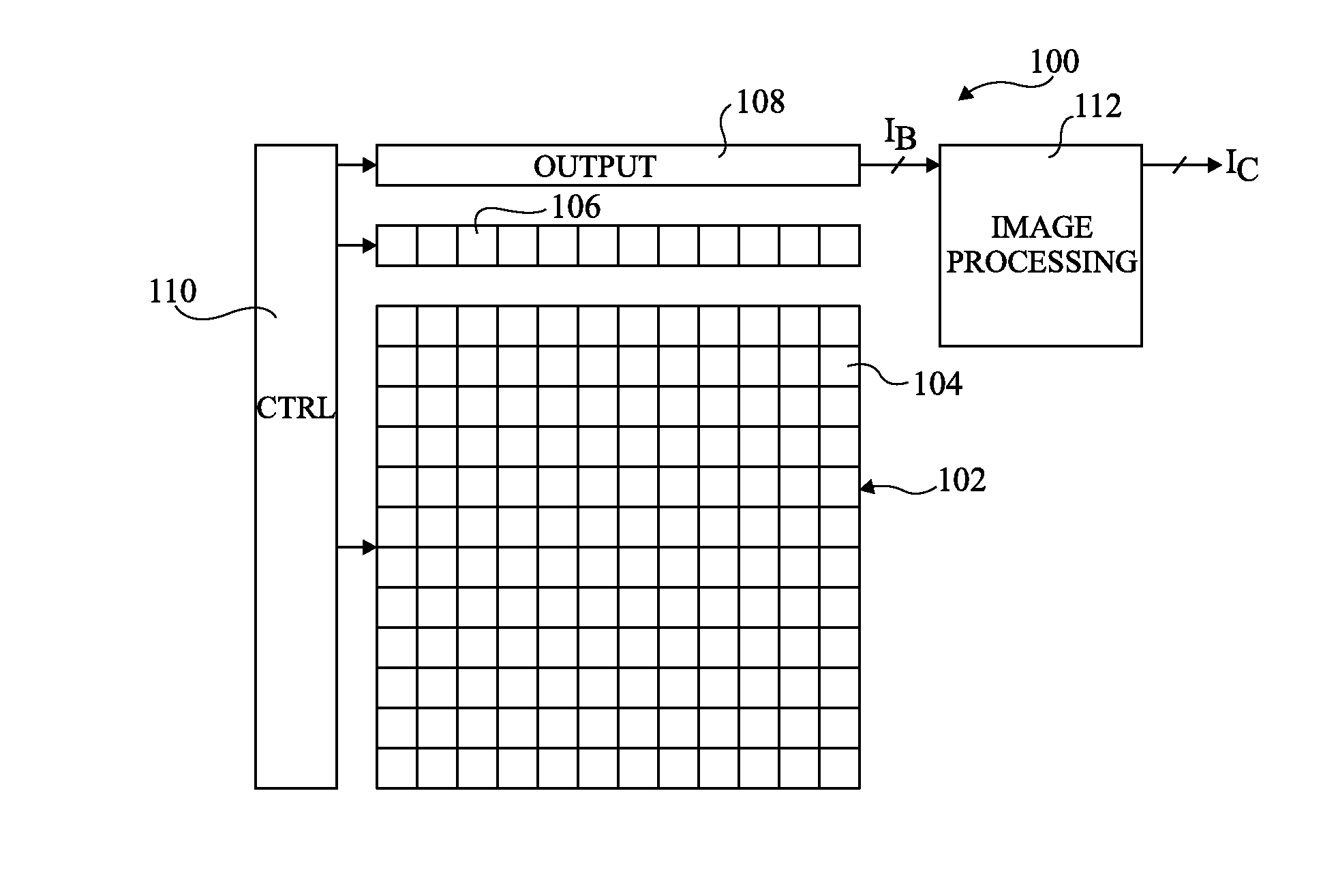
[0038]FIG. 1 illustrates an IR imaging device 100 comprising a pixel array 102 sensitive to IR light. For example, in some embodiments the pixel array is sensitive to long-wave IR light, such as light with a wavelength of between 7 and 13 μm.

[0039]For ease of illustration, a pixel array 102 of only 144 pixels 104, arranged in 12 rows and 12 columns, is illustrated in FIG. 1. In alternative embodiments the pixel array 102 could comprise any number of rows and columns of pixels. Typically, the array for example comprises 640 by 480, or 1024 by 768 pixels.

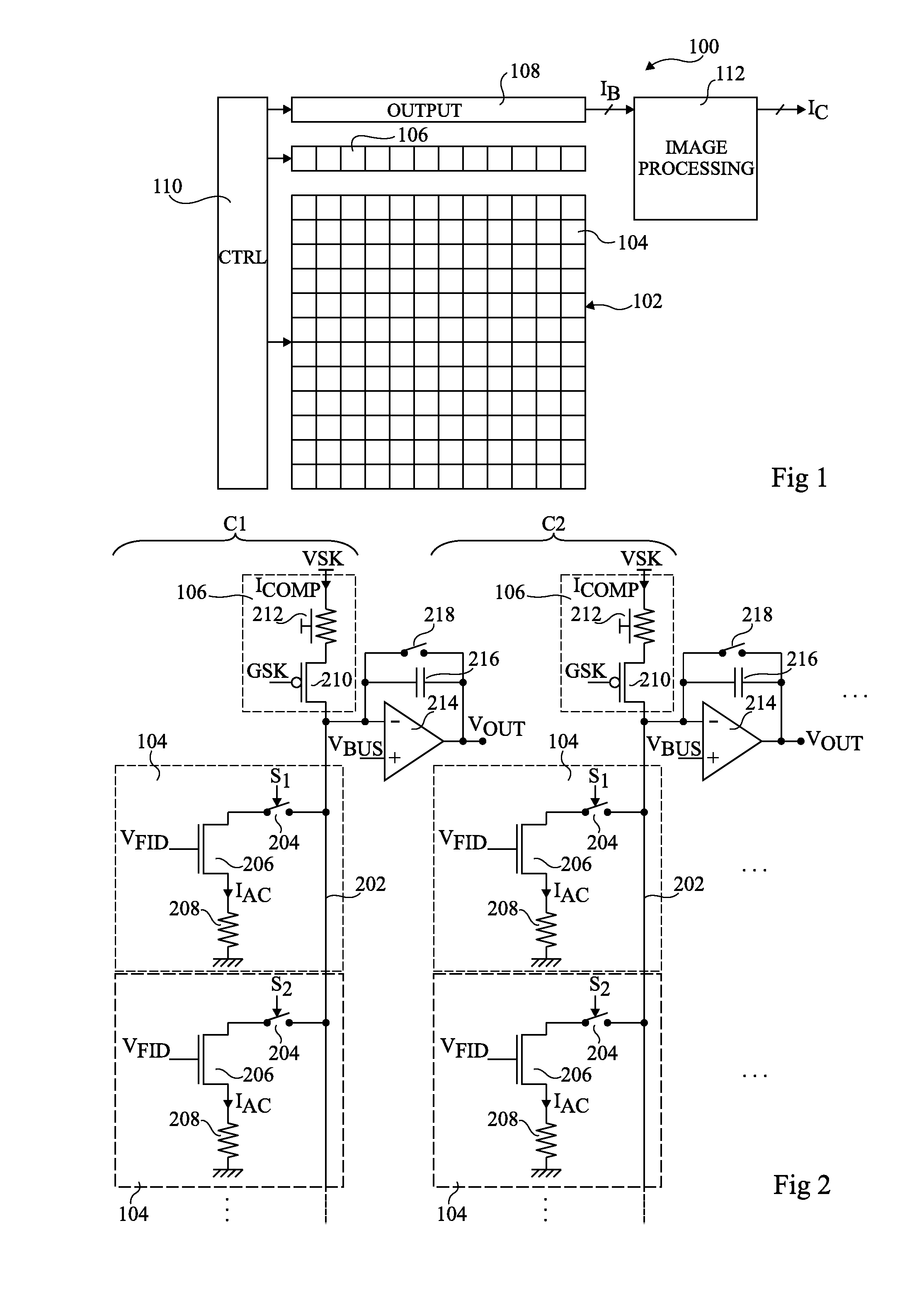
[0040]Each column of pixels of the array 102 is associated with a corresponding reference structure 106. Though not functionally a p...


PUM


Abstract

The invention concerns a method of image processing involving: receiving, by a processing device, an input image (IB) captured by a pixel array sensitive to infrared radiation; determining, based on the input image and on a column component vector (VCOL), a first scale factor (α) by estimating a level of the column spread present in the input image; generating column offset values (α.VCOL(y)) based on the product of the first scale factor with the values of the vector; determining, based on the input image and on a 2D dispersion matrix (IDISP), a second scale factor (β) by estimating a level of the 2D dispersion present in the input image; generating pixel offset values (β.IDISP(x,y)) based on the product of the second scale factor with the values of the matrix; and generating a corrected image (IC′) by applying the column and pixel offset values.

Description

CROSS-REFERENCE TO RELATED APPLICATIONS[0001]The present application claims priority under 35 U.S.C. §119 to French application Serial Number 14 / 53917, filed Apr. 30, 2014, and of European patent Application Serial Number 15164692.4, filed Apr. 22, 2015, the disclosures of which are incorporated by reference herein.BACKGROUND OF THE INVENTION[0002]1. Field of the Invention[0003]The present disclosure relates to the field of infrared image sensors, and in particular to a method and device for performing offset and gain corrections in an image captured by an array of pixels sensitive to infrared light.[0004]2. Description of the Related Art[0005]In the field of infrared (IR) imaging, performing offset correction in captured images, without the use of a shutter or shutter-like hardware, presents a major challenge for uncooled IR imaging devices, such as microbolometers, and also for cooled IR imaging devices. Such imaging devices comprise an array of IR-sensitive detectors forming a pi...

Claims


Application Information

Patent Timeline
Patent Type & Authority Applications(United States)
IPC IPC(8): H04N5/365H04N3/09H04N5/33G06V30/144
CPCH04N5/3651H04N3/09H04N5/33G01J5/22G01J2001/444G01J1/44G01J5/24H04N25/67H04N25/674G06T7/30G06V30/144H04N25/671
Inventor SARAGAGLIA, AMAURYDURAND, ALAIN
Owner LYNRED
Why Eureka
Try Eureka