Nonuniformity correction method and system of infrared image

A non-uniformity correction, infrared image technology, used in image enhancement, image analysis, image data processing and other directions, can solve the problems of poor infrared image quality, poor imaging quality, large calculation errors, etc., to achieve good infrared imaging quality, easy to use. Realize the effect of small amount of computation

Active Publication Date: 2017-10-17
EZHOU INST OF IND TECH HUAZHONG UNIV OF SCI & TECH +1
View PDF6 Cites 17 Cited by
  • Summary
  • Abstract
  • Description
  • Claims
  • Application Information

AI Technical Summary

Problems solved by technology

In the process of infrared imaging, the non-uniformity of the infrared image is easily affected by the temperature of the detector and the change of the image scene, which seriously reduces the imaging quality of the infrared detector. Therefore, it is necessary to correct the non-uniformity of the infrared image to eliminate the influence of external factors on the imaging quality impact
[0003] Infrared image non-uniformity correction usually adopts a shutterless calibration algorithm, and there are many existing shutterless calibration algorithms, refer to the shutterless correction algorithm based on the minimum square sum of adjacent pixel differences proposed by the patent number GB2445254A, the algorithm first needs Dozens of images of uniform background are collected within the working temperature range of the detector, and then the corresponding offset background is calculated. During real-time correction, the real-time offset correction parameters are obtained by calculating the weighted sum of all offset backgrounds. The weighted The coefficients can be continuously adaptively

Method used


Image

  • Nonuniformity correction method and system of infrared image
  • Nonuniformity correction method and system of infrared image
  • Nonuniformity correction method and system of infrared image

Examples


Embodiment Construction

[0048] The present invention will be further described in detail below in conjunction with the drawings and embodiments.

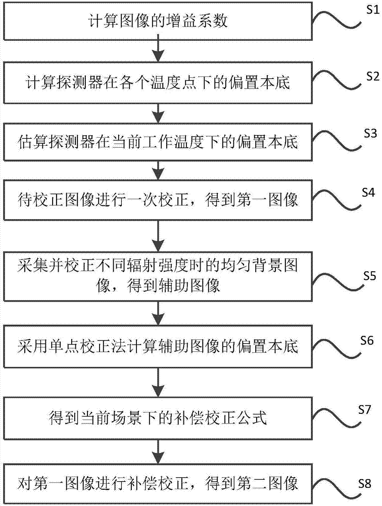
[0049] The embodiment of the present invention provides a method for correcting infrared image non-uniformity, including the steps:

[0050] Using the non-uniformity correction method based on the temperature of the detector, the image to be corrected is corrected once to obtain a first image;

[0051] Collect uniform background images of the image to be corrected at multiple different radiation intensities, and perform non-uniformity correction based on the detector temperature for each uniform background image at different radiation intensities to obtain multiple auxiliary images at different radiation intensities;

[0052] The single-point correction method is used to calculate the offset background of the auxiliary image, and the compensation correction model is established according to the weighting method. The weighting coefficient of the auxiliary image in t...


PUM


Abstract

The invention, which relates to the field of infrared image processing, discloses a nonuniformity correction method and system of an infrared image. The method comprises: carrying out primary correction on a to-be-corrected image to obtain a first image; collecting uniform background images of the to-be-corrected image at a plurality of different radiation intensities and carrying out correction on the uniform background images at different radiation intensities to obtain a plurality of auxiliary images at different radiation intensities; and calculating offset backgrounds of the auxiliary images, establishing a compensation correction model at a current scene based on a weighing method, calculating weighting coefficients of the auxiliary images in the compensation correction model by enabling a quadratic sum of a pixel difference between the image after compensation correction and an expected image to be minimized, obtaining a compensation correction formula at the current scene, and carrying out compensation correction on the first image to obtain a second image. With the method provided by the invention, the influence on infrared imaging by the temperature change of the detector and the scene change can be eliminated and the infrared imaging quality can be improved.

Description

Technical field [0001] The invention relates to the field of infrared image processing, in particular to a method and system for correcting infrared image non-uniformity. Background technique [0002] With the continuous development of infrared imaging technology, it has been widely used in civilian, military and other fields. In the infrared imaging process, the non-uniformity of the infrared image is easily affected by the temperature of the detector and the change of the image scene, which seriously reduces the imaging quality of the infrared detector. Therefore, it is necessary to correct the non-uniformity of the infrared image to eliminate external factors for imaging The impact of quality. [0003] Infrared image non-uniformity correction usually uses shutterless calibration algorithm. There are many existing shutterless calibration algorithms. Refer to the patent number GB2445254A based on the minimum square sum of adjacent pixel difference correction algorithm. This algor...

Claims


Application Information

Patent Timeline
IPC IPC(8): G01J5/00G06T5/00
CPCG06T5/001G01J5/00G01J2005/0077G06T2207/10048G01J5/80
Inventor 周波梁琨
Owner EZHOU INST OF IND TECH HUAZHONG UNIV OF SCI & TECH
Why Eureka
Try Eureka