Method and apparatus for cooling hot-rolled steel strip (as amended)

a technology of hot-rolled steel and cooling apparatus, which is applied in the direction of work cooling devices, metal rolling arrangements, manufacturing tools, etc., can solve the problems of poor stiffness of thin steel strips having a thickness of about 1.2 mm, difficulty, and high passing speed, so as to achieve the same strength, the effect of easy regulation of cooling rate and the lik

Active Publication Date: 2015-11-12
JFE STEEL CORP
View PDF12 Cites 4 Cited by
  • Summary
  • Abstract
  • Description
  • Claims
  • Application Information

AI Technical Summary

Benefits of technology

[0030]The present invention can provide a cooling technique that, in the cooling of a hot-rolled steel strip, regulates the amount of cooling water in a two-stage manner for each set of headers in the width direction and changes the rate at which the steel strip is cooled, in a multistage manner by a simple method, and that is effective particularly in cooling the lower surface of the steel strip, where space is narrow.
[0031]By applying the present invention to the cooling after finish rolling in the hot-rolled steel strip manufacturing line, the cooling rate can be easily regulated. Therefore, various hot-rolled steel strips can be made. In addition, it is made possible to manufacture hot-rolled steel strips having the same strength, toughness, and the like as those of conventional ones without adding a special element.

Problems solved by technology

If the cooling rate is too high, this workability may be impaired.
Unfortunately, difficulties occur.
In particular, a thin steel strip having a thickness of about 1.2 mm has poor stiffness and provides high passing speed.

Method used


Image

  • Method and apparatus for cooling hot-rolled steel strip (as amended)
  • Method and apparatus for cooling hot-rolled steel strip (as amended)
  • Method and apparatus for cooling hot-rolled steel strip (as amended)

Examples


examples

[0073]Examples of the present invention will be described.

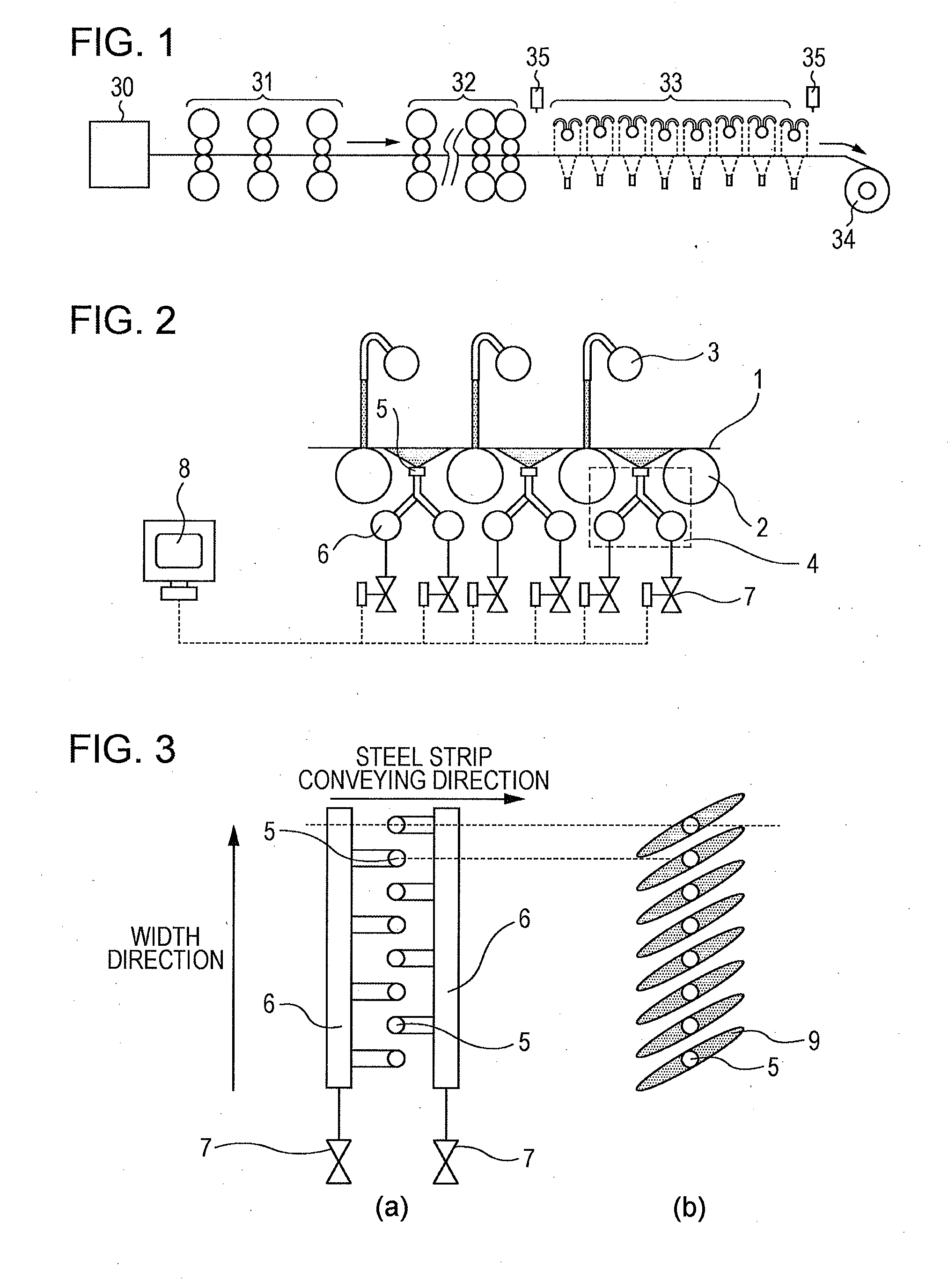
[0074]In the examples, in the hot-rolled steel strip manufacturing line of FIG. 1, a slab having a thickness of 250 mm was heated up to 1200° C. in the heating furnace 30 and was subsequently rolled by the rough rolling mill group 31 and the finish rolling mill group 32 so as to be 3.2 mm thick and 1200 mm wide, and was then cooled by the cooling apparatus 33, and was coiled by the coiler 34. The temperature after the completion of rolling and after the completion of cooling was measured by the radiation thermometer 35. The temperature after the completion of rolling was 850° C., and the temperature after the completion of cooling was 550° C. The steel strip passing speed during cooling was 550 mpm.

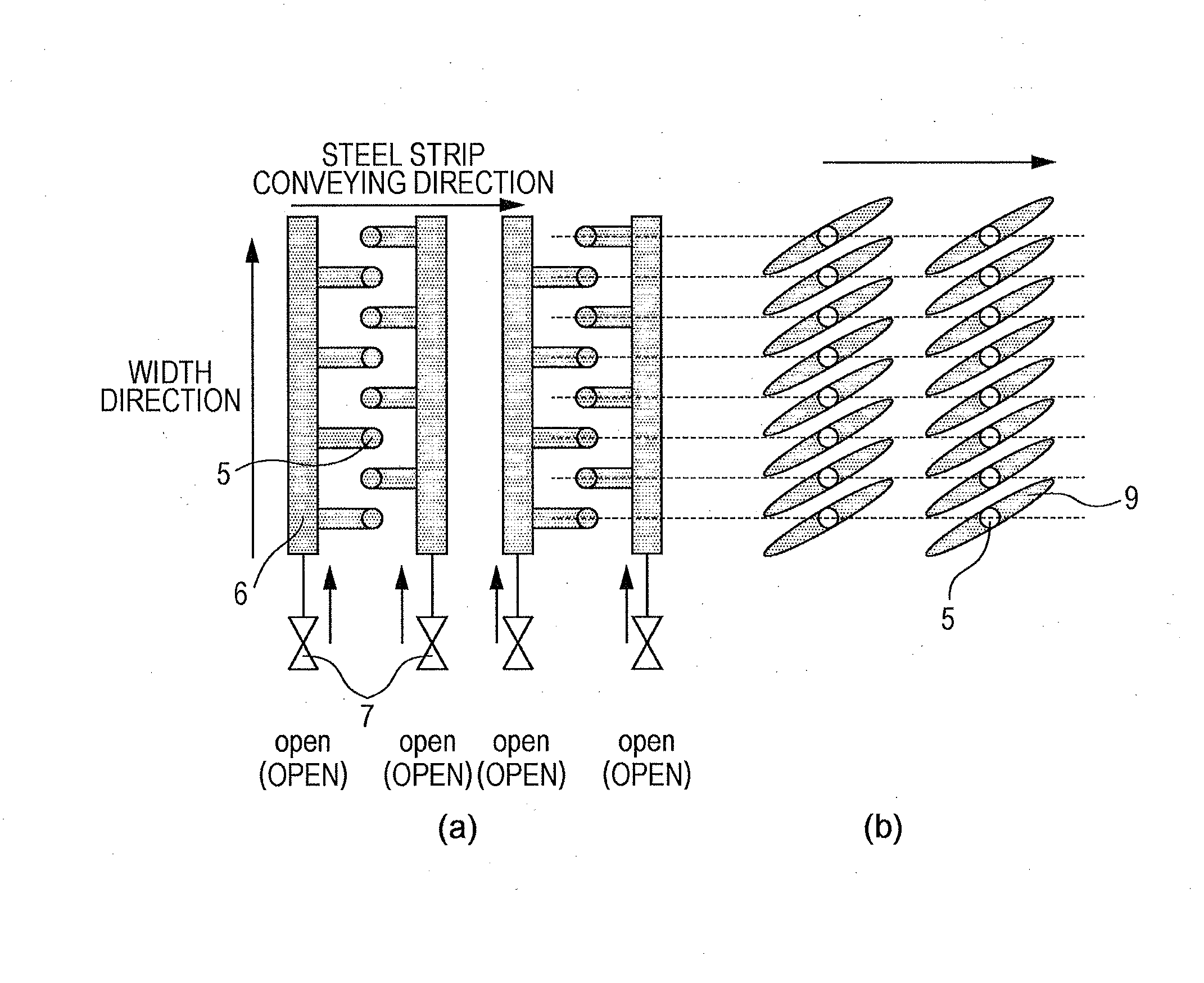
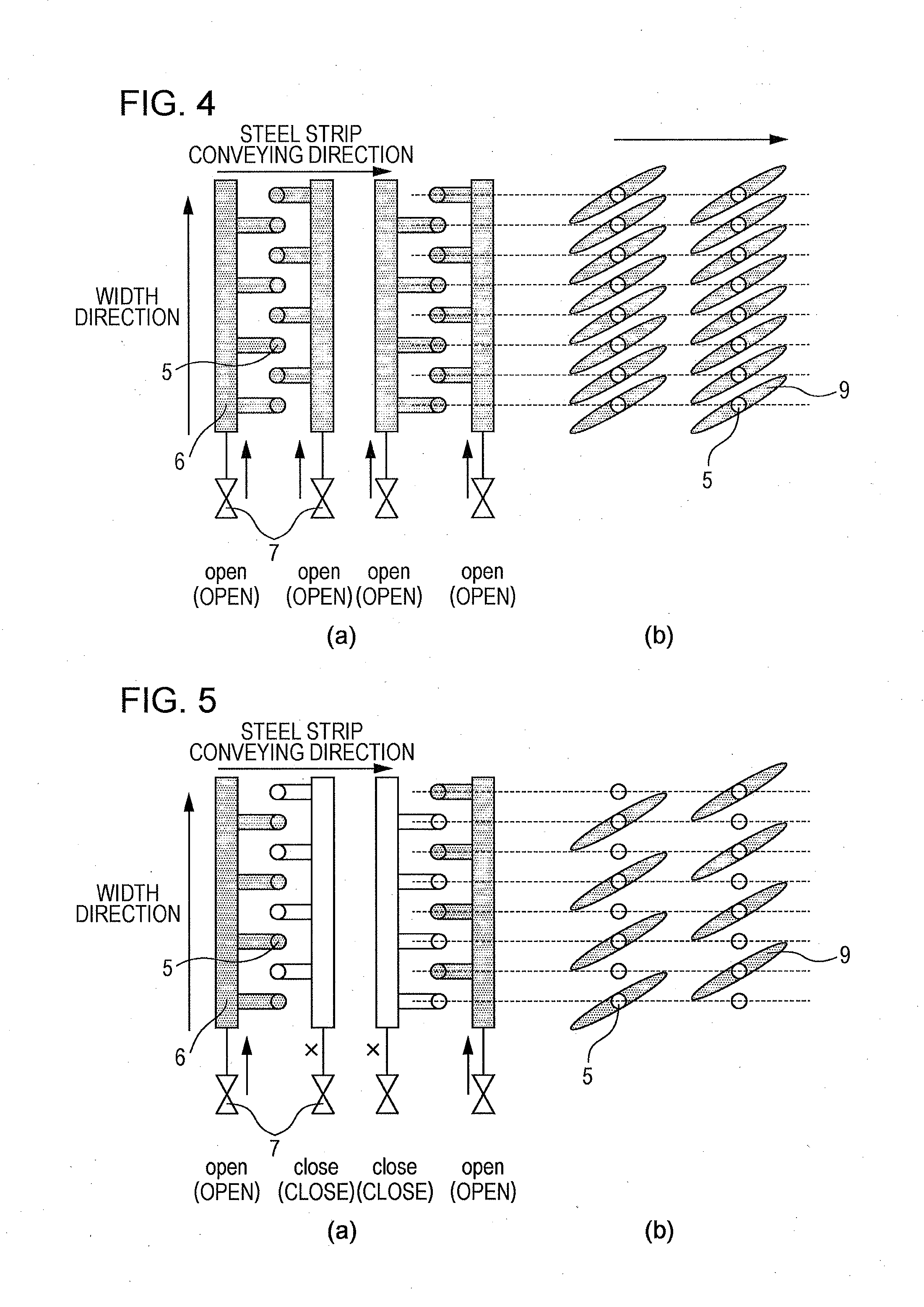
[0075]As shown in FIG. 2, the cooling apparatus 33 included pipe laminar nozzles 3 for the upper surface, and spray cooling apparatuses 4 of the present invention for the lower surface. The flow rate density of spray per unit area ...


PUM

PropertyMeasurementUnit
thicknessaaaaaaaaaa
thicknessesaaaaaaaaaa
thicknessaaaaaaaaaa

Abstract

Provided are a cooling method and a cooling apparatus that, in the cooling of a hot-rolled steel strip, regulates the amount of cooling water in a two-stage manner for each set of headers in the width direction and changes the rate at which the steel strip is cooled, in a multistage manner by a simple method, and that is effective particularly in cooling the lower surface of the steel strip, where space is narrow. The spray nozzles 5 are arranged in a row in the width direction of the steel strip at a predetermined pitch. Two systems of cooling headers 6 are arranged for one set so that spray nozzles 5 adjacent in the width direction can be supplied with cooling water from different pipe systems, and a spray valve 7 is attached to each cooling header 7 so that spraying / stop of spraying of cooling water can be individually performed.

Description

TECHNICAL FIELD[0001]The present invention relates to a cooling method and a cooling apparatus that make it possible to, when a hot-rolled steel strip is cooled by controlled cooling in a hot-rolled steel strip manufacturing line, regulate the rate at which the hot-rolled steel strip is cooled, in a multistage manner.BACKGROUND ART[0002]A hot-rolled steel strip (hereinafter also simply referred to as a steel strip) is manufactured by rolling a heated slab such that the slab has a desired size. In this case, the hot-rolled steel strip is cooled using cooling water (water cooling) by a cooling apparatus during hot rolling (rough rolling, finish rolling) or after finish rolling. The purpose of this water cooling is to mainly control deposit or transformation structure of the steel strip and to regulate the quality of material so that intended strength, ductility, and the like can be obtained. In particular, accurately controlling at a predetermined temperature in the cooling after fini...

Claims


Application Information

Patent Timeline
Patent Type & Authority Applications(United States)
IPC IPC(8): B21B45/02
CPCB21B45/0218B21B45/0233
Inventor UEOKA, SATOSHICHIBA, TAKESHIIBUKI, KAZUYAIIJIMA, YOSHITSUGU
Owner JFE STEEL CORP
Why Eureka
Try Eureka