Method and apparatus for handling material in a pneumatic materials handling system

Inactive Publication Date: 2015-11-12
MARICAP OY
View PDF51 Cites 3 Cited by
  • Summary
  • Abstract
  • Description
  • Claims
  • Application Information

AI Technical Summary

Benefits of technology

[0013]The solution according to the invention has a number of important advantages. By means of the invention a particularly efficient solution for the handling of material, more particularly for pneumatic pipe transport, is achieved. With the solution according to the invention, it is possible to organize, convey and, if necessary, shape the material to be fed in to fit into a conveying channel that is smaller in its inner dimensions than the input chute. The power requirement of the rotary shaper according to the invention is smaller than shapers according to prior art. With the solution according to the invention, the material to be fed in from an input chute can be arranged one unit at a time to be conveyed from the chute via t

Problems solved by technology

In the solution according to the publication large output powers are typically needed, especially in situations in which the device is used to cut or fine-grind a material, in which case the energy cons

Method used


Image

  • Method and apparatus for handling material in a pneumatic materials handling system
  • Method and apparatus for handling material in a pneumatic materials handling system
  • Method and apparatus for handling material in a pneumatic materials handling system

Examples


Embodiment Construction

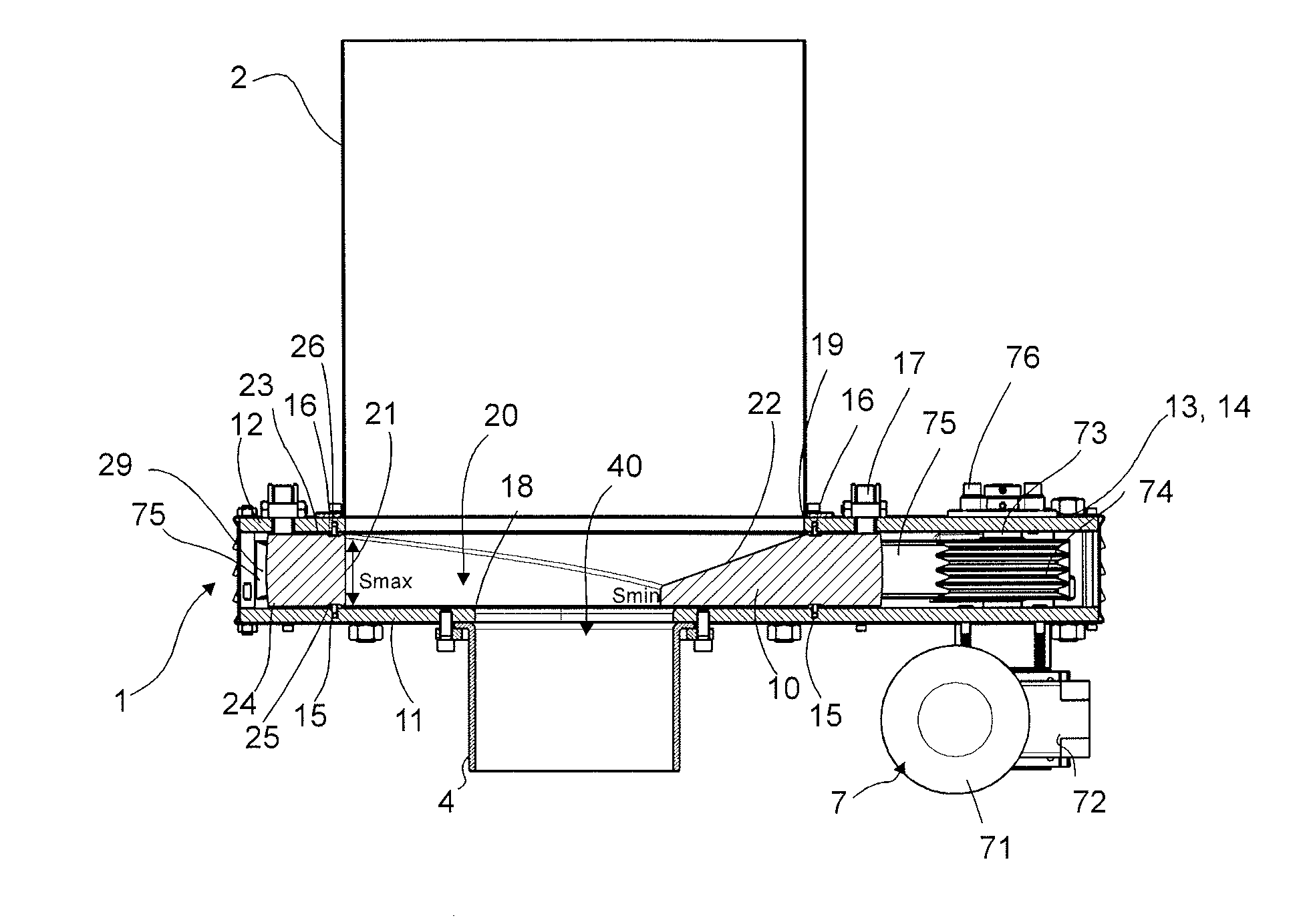
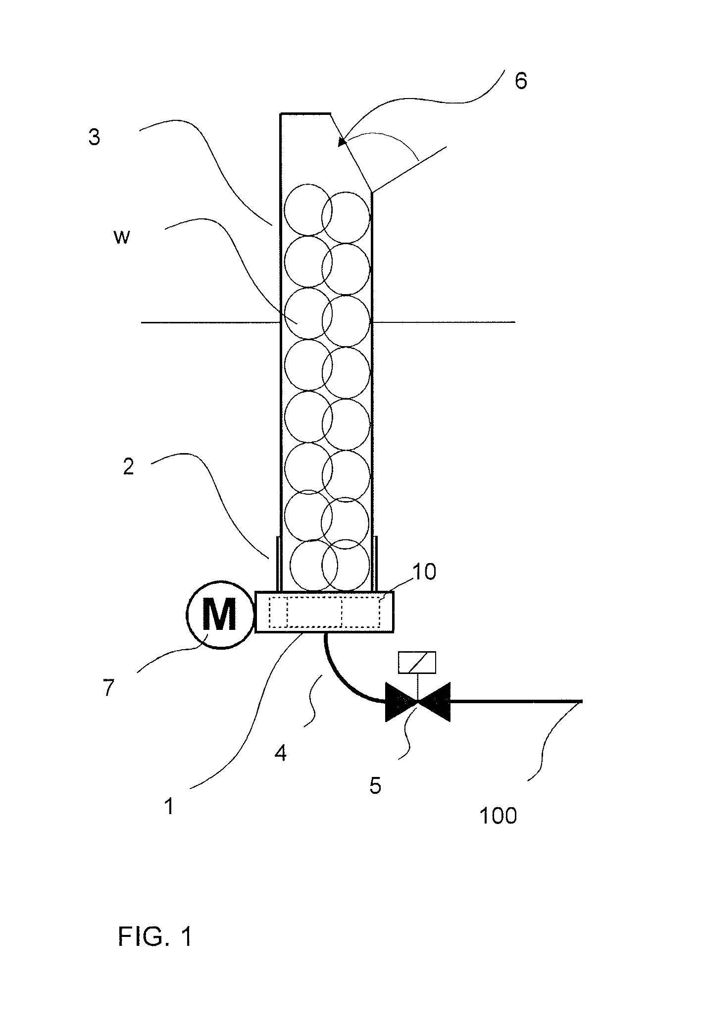
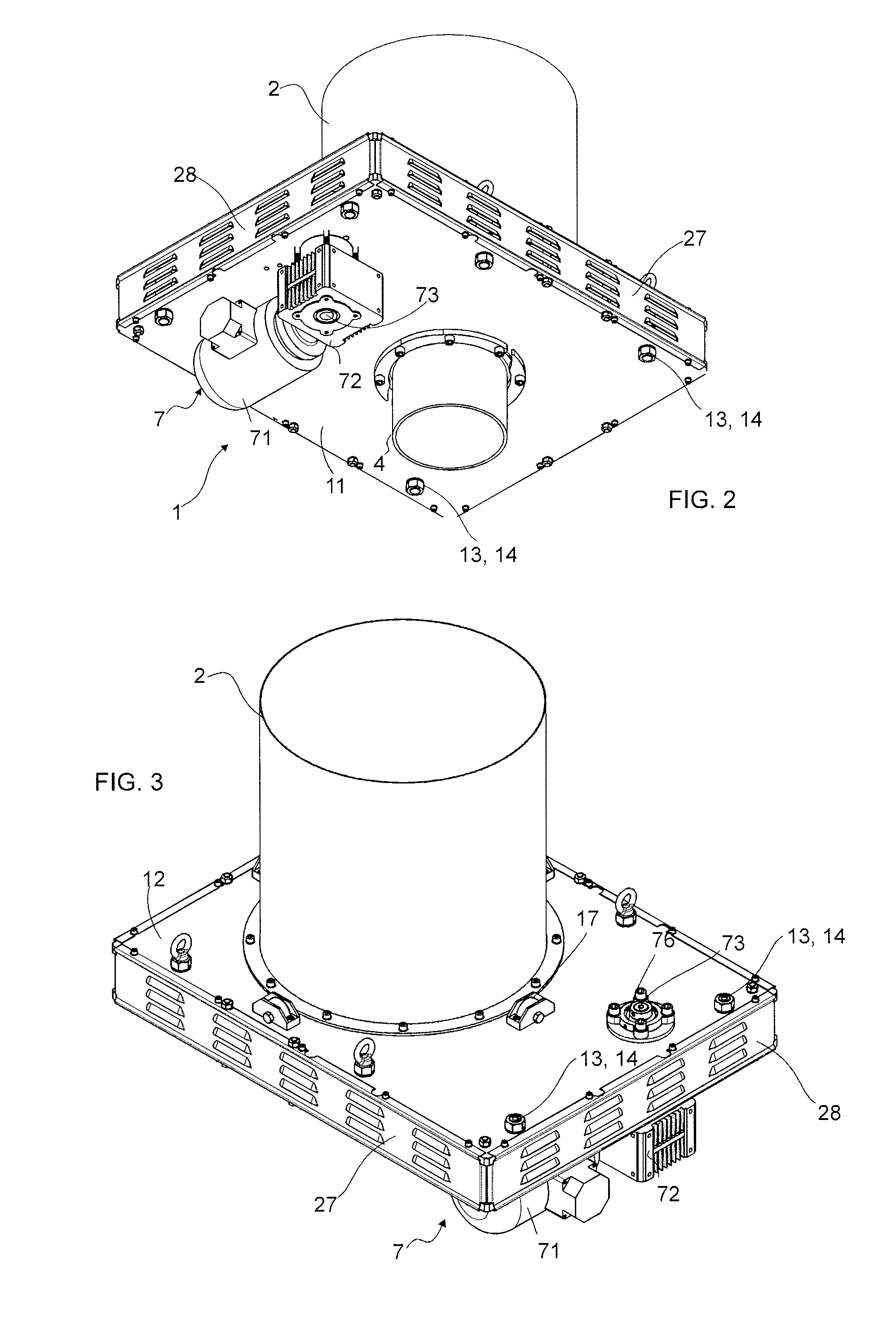
[0026]FIG. 1 presents a simplified diagram of one embodiment of the solution according to the invention, in which the rotary shaper device 1 is arranged in connection with a feeder channel 2, into which material is conducted e.g. from an input point 3, such as from an input chute, refuse chute or corresponding. The feeder channel 2 is e.g. a tubular part, inside the wall of which remains space for the material w to be fed in. The material w, such as household waste or other waste packed into bags, is fed, e.g. from an input aperture 6, into the input point 3 and from there onwards, via the feeder channel 2, into the rotary shaper 1. An openable and closable hatch, which is open in the situation of the figure, is in connection with the input aperture 6 in FIG. 1. The input point and feeder channel are in their dimensions, in their cross-sectional area, such that the material w, more particularly waste packed into bags, to be fed in fits into them side by side and one above the other....


PUM


Abstract

Method for handling material in a pneumatic pipe transport system, in which material, such as waste material, is input from an input aperture of an input point (3), such as from the input aperture of a refuse chute or of some other input point, and is conducted along a feeder channel (2) with a shaper device (1) arranged in connection with the input point or in the proximity of it, in which case the material to be handled is conducted into the shaper device and/or through it by the aid of at least partly gravity and/or the suction and/or a pressure difference of the pneumatic pipe transport system. In the method the material is handled with one handling means (10) in a shaper device (1), which handling means is rotated around an axis of rotation when handling material and which handling means comprises an aperture (20), which is arranged eccentrically with respect to the axis of rotation of the handling means, that the rotatable handling means (10) arranges the material to be infed into the proximity of the output aperture and, if necessary, shapes the material, together with at least an edge (18) of the output aperture of the rotary shaper and/or the wall of the output channel (4), when the handling means (10) is rotated with a drive device (7).

Description

BACKGROUND OF THE INVENTION[0001]The object of the invention is a method as defined in the preamble of claim 1.[0002]Another object of the invention is an apparatus as defined in the preamble of claim 9.[0003]The invention relates generally to materials handling systems, such as partial-vacuum transporting systems, more particularly to the collection and conveying of wastes, such as to the conveying of household wastes.[0004]Systems wherein wastes are conveyed in piping by means of an air current produced by a pressure difference or suction are known in the art. In these, wastes are conveyed long distances in the piping. It is typical to these systems that a partial-vacuum apparatus is used to achieve a pressure difference, in which apparatus a partial vacuum is achieved in the conveying pipe with partial-vacuum generators, such as with vacuum pumps or with an ejector apparatus. A conveying pipe typically comprises at least one valve means, by opening and closing which the replaceme...

Claims


Application Information

Patent Timeline
IPC IPC(8): B65F5/00B65G53/40
CPCB65G53/40B65F5/005B02C18/12B02C23/02B30B3/04B65G53/04
Inventor SUNDHOLM, GORAN
Owner MARICAP OY
Why Eureka
Try Eureka