
Fiber sensor assembly

a fiber sensor and assembly technology, applied in the field of bearing, can solve the problems of affecting the quality of deformation measurements in an adverse way, obviating the necessity of a connection layer, etc., and achieve the effect of reducing the relative movement of the fiber sensor and increasing the accuracy of subsequent deformation measurements

Inactive Publication Date: 2015-11-12
AB SKF
View PDF6 Cites 8 Cited by
  • Summary
  • Abstract
  • Description
  • Claims
  • Application Information

AI Technical Summary

Benefits of technology

The invention provides a bearing with a fiber sensor that is securely attached to the bearing ring using a clamping force. This eliminates any need for a separate connection layer and ensures accurate deformation measurements. The bearing ring has a predefined groove that allows for easy implementation of mass production with standardized manufacturing processes. A channel is added for increased sensitivity by reducing material thickness between the sensor and the rolling elements. This channel can be formed by continuous or intermittent areas of increased thickness around the circumference of the bearing ring.

Problems solved by technology

Furthermore, the presence of the clamping force obviates the necessity for a connection layer during use of the bearing ring.
Such a connection layer can deteriorate during use, thereby influencing the quality of the deformation measurements in an adverse way.

Method used


Image

  • Fiber sensor assembly
  • Fiber sensor assembly
  • Fiber sensor assembly

Examples


Embodiment Construction

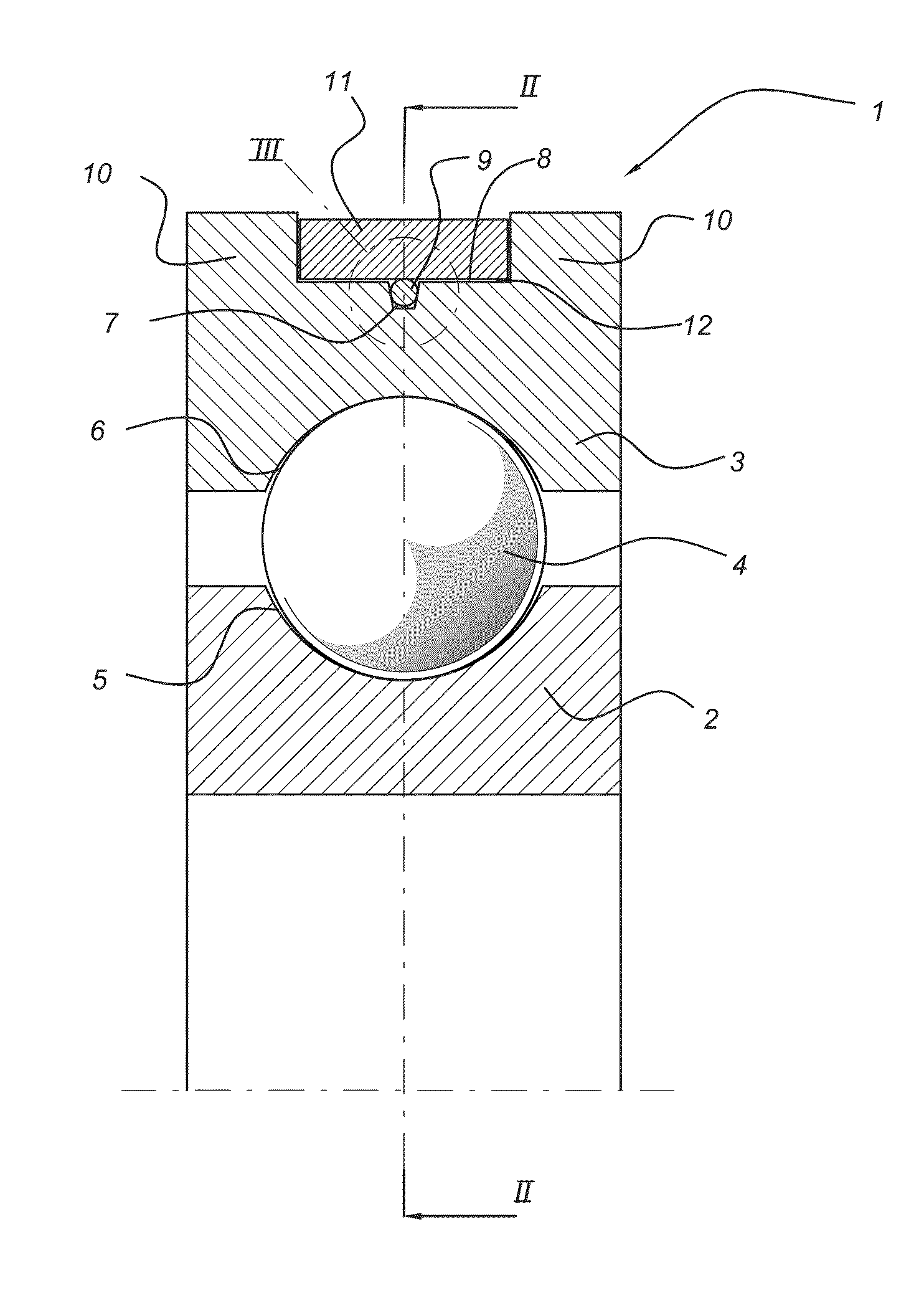
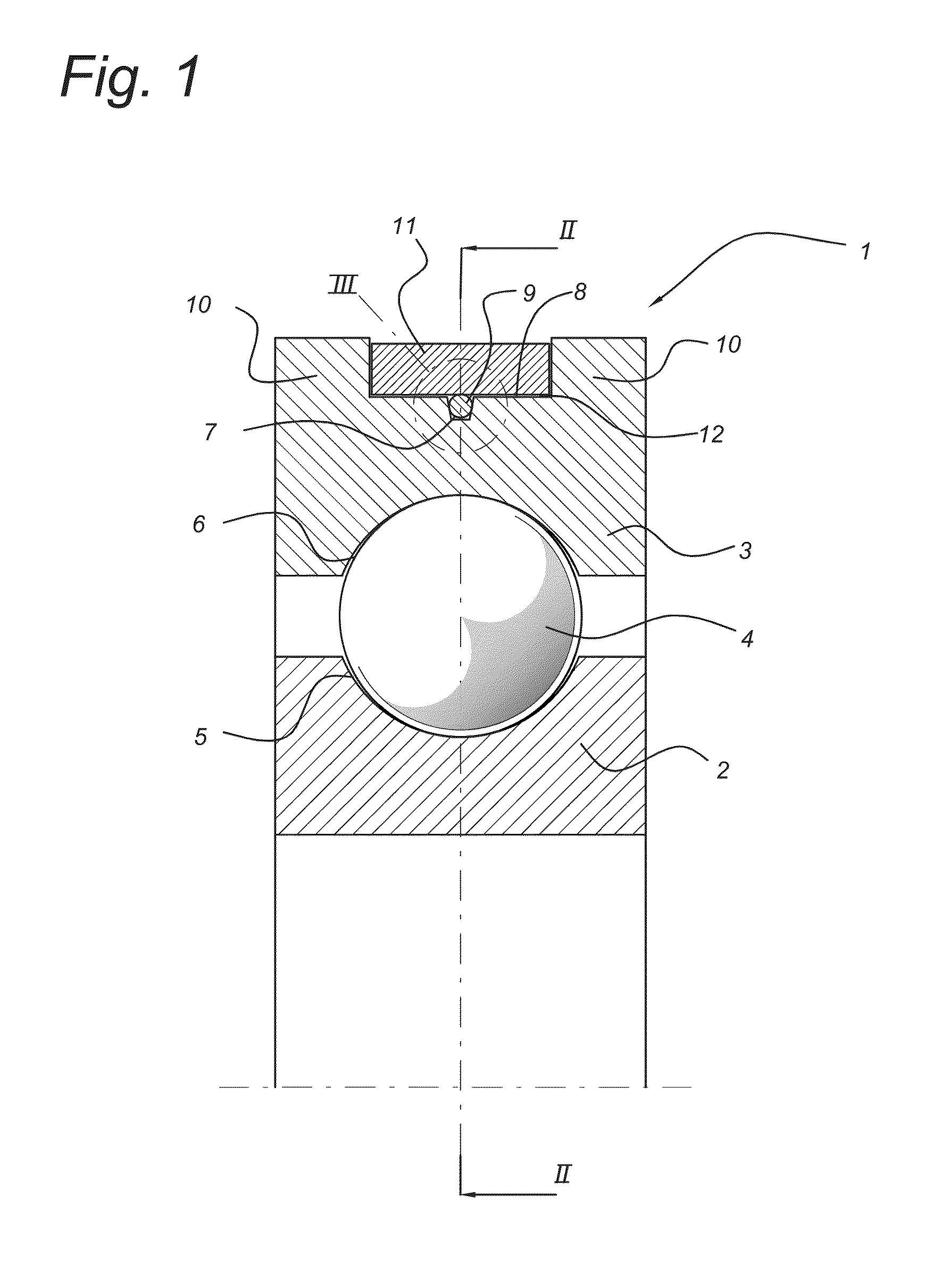
[0027]FIG. 1 shows an axial cross-section of a bearing 1 comprising an inner bearing ring 2 having an inner raceway 5, and an outer bearing ring 3 having an outer raceway 6. In between the inner and outer rings 2, 3, rolling elements 4 are provided such that the inner and outer bearing rings 2, 3 can rotate with respect to each other. The rolling elements 4 are located in between the inner and outer raceways 5, 6.

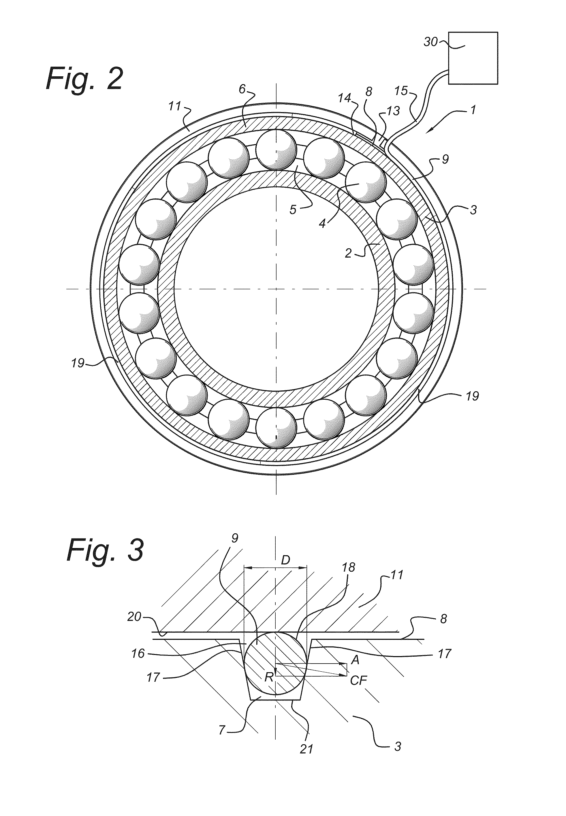
[0028]A groove 7 is provided at an outer surface 8 of the outer bearing ring 3. The groove 7 accommodates a fiber sensor 9, comprising an optical fiber. In its turn, the groove 7 is provided within a channel 12. The channel 12 is shaped as a recess between two sidewalls 10 forming an increase in thickness of the outer bearing ring 3.

[0029]The fiber sensor 9 is accommodated in the groove 7 and connected to the outer bearing ring by means of a clamping ring 11. The clamping ring 11 is accommodated in the channel 12. Clamping ring 11 exerts a clamping force CF onto the fiber s...


PUM

PropertyMeasurementUnit
Forceaaaaaaaaaa
Diameteraaaaaaaaaa
Widthaaaaaaaaaa

Abstract

A bearing which includes a bearing ring and rolling elements. The bearing ring includes an outer surface, having a groove around a circumference of the outer surface, wherein the groove is adapted to accommodate a fiber sensor. The bearing further comprises a clamping element, wherein the clamping element retains the fiber sensor with a clamping force acting in a radial direction of the bearing ring such that the fiber sensor intimately engages the bearing ring. Due to the clamping force, relative movement of the fiber sensor can be reduced.

Description

CROSS REFERENCE TO RELATED APPLICATIONS[0001]This is a U.S. National Stage Application claiming the benefit of International Application Number PCT / EP2012 / 075555 filed on 14 Dec. 2012 (14 Dec. 2012), which is incorporated herein by reference in its entirety. The 30 month anniversary of the filing date of the International Patent Application is 14 Jun. 2012 (14 Jun. 2015), which falls on a Sunday. Therefore, Applicant is afforded until the next business day (Monday, 15 Jun. 2015) to file the National Stage Application.FIELD OF THE INVENTION[0002]The invention relates to a bearing comprising a fiber sensor assembly and furthermore to a method for connecting such a fiber sensor to a bearing.DESCRIPTION OF THE RELATED ART[0003]Bearings are a very important component in rotating machinery. If a bearing fails, then the functionality of the machinery can break down. In some applications it can be very difficult or extremely expensive to replace a failed bearing outside regular scheduled ma...

Claims


Application Information

Patent Timeline
IPC IPC(8): F16C41/00F16C43/04
CPCF16C41/00Y10T29/4968F16C43/04F16C19/522G01M11/085G01D5/353G01M13/04G02B6/3636G01L1/242G01L1/246G01L5/0009G01B11/16G01D5/35316G01D11/02F16C19/06
Inventor HERDIER, ROMAINLANG, DEFENGYANG, HONGYU
Owner AB SKF
Learn More