Compensation methods for active magnetic sensor systems

Inactive Publication Date: 2015-11-12
TORQUE & MORE TAM
View PDF6 Cites 23 Cited by
  • Summary
  • Abstract
  • Description
  • Claims
  • Application Information

AI Technical Summary

Benefits of technology

[0046]It should be noted that the above features may also be combined. The combination of the

Problems solved by technology

Measuring forces is a challenge, as the environment of the measurement may provide a lot of disturbing effects.
The challenge here will be that when the test object becomes very large and therefore heavy, it becomes increasingly more difficult to achieve the quality of de-magnetization (or degaussing) with an increasing size of the test object.
The electrical energy required to degauss properly e.g. a wind turbine shaft is so big that it is no longer practical or payable to degauss such ob

Method used


Image

  • Compensation methods for active magnetic sensor systems
  • Compensation methods for active magnetic sensor systems
  • Compensation methods for active magnetic sensor systems

Examples


Embodiment Construction

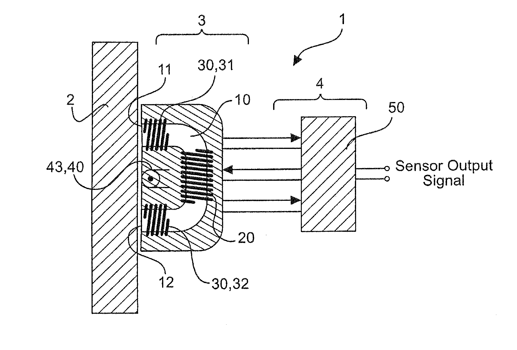
[0061]The active mechanical force sensor technology is capable to measure mechanical forces that are applied to a test object or object to be measured. In the following this sensing technology will be called active sensor, active sensing technology or active mechanical force sensor and is capable measure the following mechanical forces: torque, bending in x- and in y-direction (direction of the beam is the z-direction), shear forces and axial load.

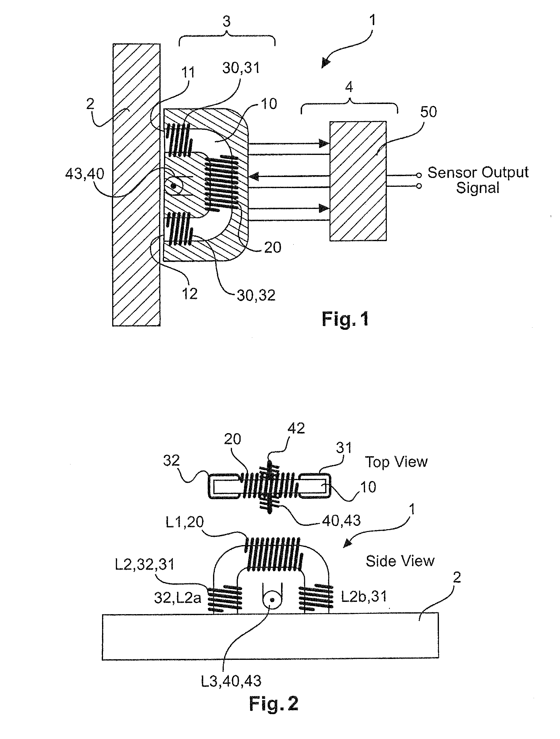
[0062]FIG. 1 illustrates one of several design options for an active sensing module 3. The active mechanical force sensor 1 comprises an active sensing module 3 that will be placed nearest the test object 2, where the measurements should be taken from, and the sensor electronics 4, also called evaluation unit. The sensor electronics 4 is connected to the active sensing module 3 by a number of wires. The sensor electronics 4 can be placed together with the active sensing module 3 in the same housing (not shown). The active sensing module 3 ...


PUM


Abstract

Active Force measuring device for measuring a force impact onto a ferromagnetic object comprising a flux concentrator having a first and second ends facing the ferromagnetic object to me measured, a magnetic field generation coil arrangement being wound around the flux concentrator, wherein the magnetic field generating coil arrangement is adapted for generating a magnetic field having a main generating direction between the first end and the second end, and a magnetic field sensing arrangement, wherein the magnetic field sensing arrangement is arranged between the first end and the second end.

Description

FIELD OF THE INVENTION[0001]The present invention relates to a device for active magnetic sensing, and in particular to a device and a method for compensating influences of e.g. stray fields, movements and other magnet fields in active magnetic sensor systems.BACKGROUND OF THE INVENTION[0002]Measuring forces is a challenge, as the environment of the measurement may provide a lot of disturbing effects. When using an active mechanical force sensor on a test object that is moving or rotating, then the remaining (not degaussed) magnetic fields, inside this test object will e.g. cause a continuous modulation of the actual measured force signal. There are a number of solutions that can be applied to deal with this unwanted issue. One of these solutions may be making sure that the test object has been degaussed properly before using the sensor device. The challenge here will be that when the test object becomes very large and therefore heavy, it becomes increasingly more difficult to achie...

Claims


Application Information

Patent Timeline
IPC IPC(8): G01L1/12
CPCG01L1/127G01L1/125G01L3/102
Inventor MAY, LUTZ
Owner TORQUE & MORE TAM
Why Eureka
Try Eureka