Life prediction apparatus for electrical storage device and life prediction method for electrical storage device

a technology of life prediction apparatus and electrical storage device, which is applied in the direction of secondary cell servicing/maintenance, instruments, electrochemical generators, etc., can solve the problems of affecting the life the cost of the electrical storage device for large power supplies, and the need to withstand longer us

Inactive Publication Date: 2015-11-12
MITSUBISHI ELECTRIC CORP
View PDF8 Cites 17 Cited by
  • Summary
  • Abstract
  • Description
  • Claims
  • Application Information

AI Technical Summary

Benefits of technology

[0020]In accordance with the present invention, the life prediction formula suitable for predicting, under random operation conditions, the evaluation characteristic which is to be used for calculating the life of an electrical storage device, is derived by statistical processing based on actually measured data obtained under a plurality of operation conditions which have been set in advance according to the type of the electrical storage device. As a result, it is possible to obtain a life prediction apparatus for an electrical storage device and a life prediction method for an electrical storage device that can predict more accurately the life of the electrical storage device under random operation conditions by taking into account the type and operation conditions of the electrical storage device which affect the life of the electrical storage device.

Problems solved by technology

Electrical storage devices for use as large power supplies are more expensive and required to withstand longer use than the conventional power supplies for portable device.
However, the life of an electrical storage device is greatly affected by the material, structure and the like of the electrical storage device (referred to hereinbelow as “type of electrical storage device”) and also temperature, charge / discharge final voltage and the like (referred to hereinbelow as “operation conditions of electrical storage device”).

Method used


Image

  • Life prediction apparatus for electrical storage device and life prediction method for electrical storage device
  • Life prediction apparatus for electrical storage device and life prediction method for electrical storage device
  • Life prediction apparatus for electrical storage device and life prediction method for electrical storage device

Examples


embodiment 1

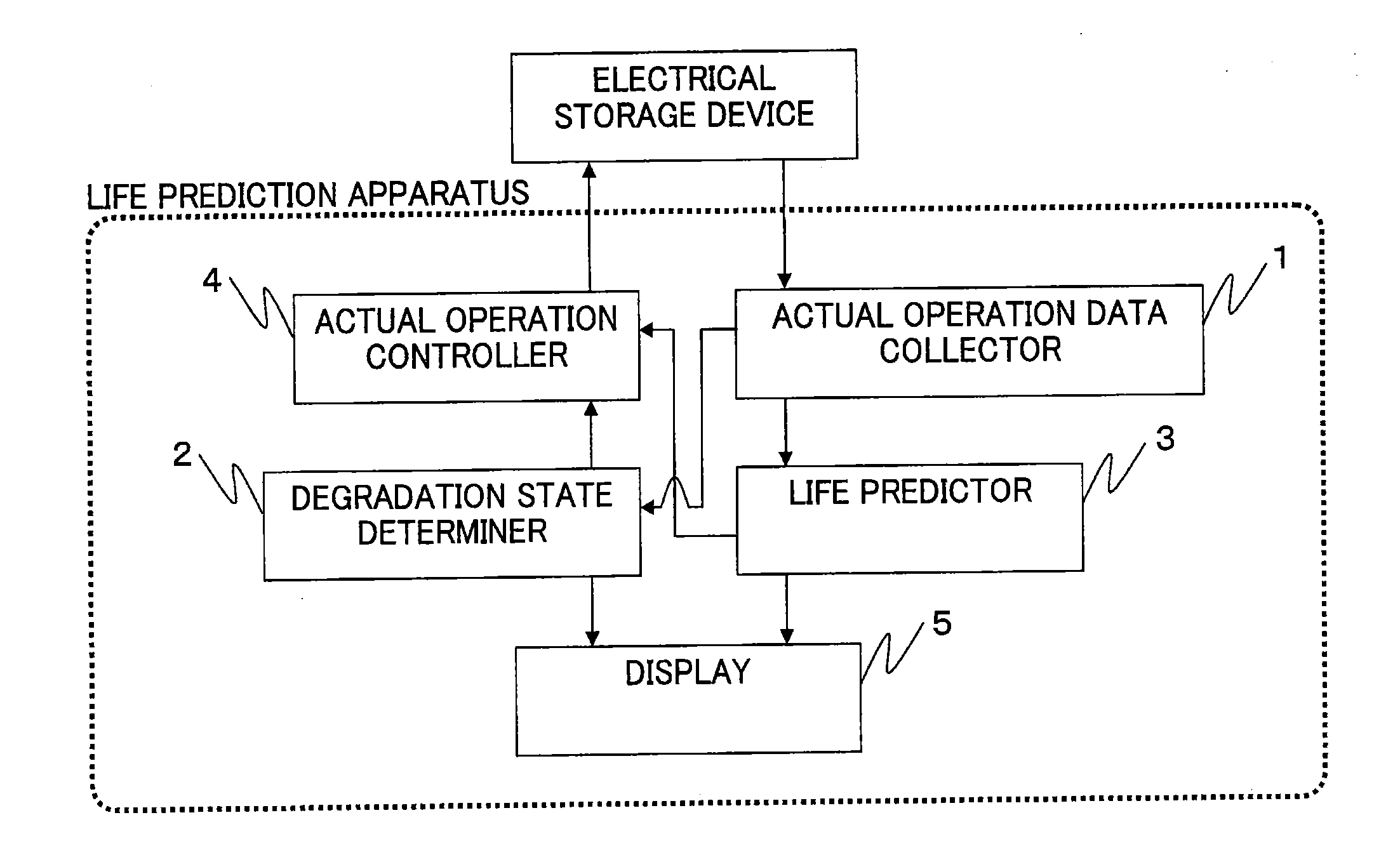
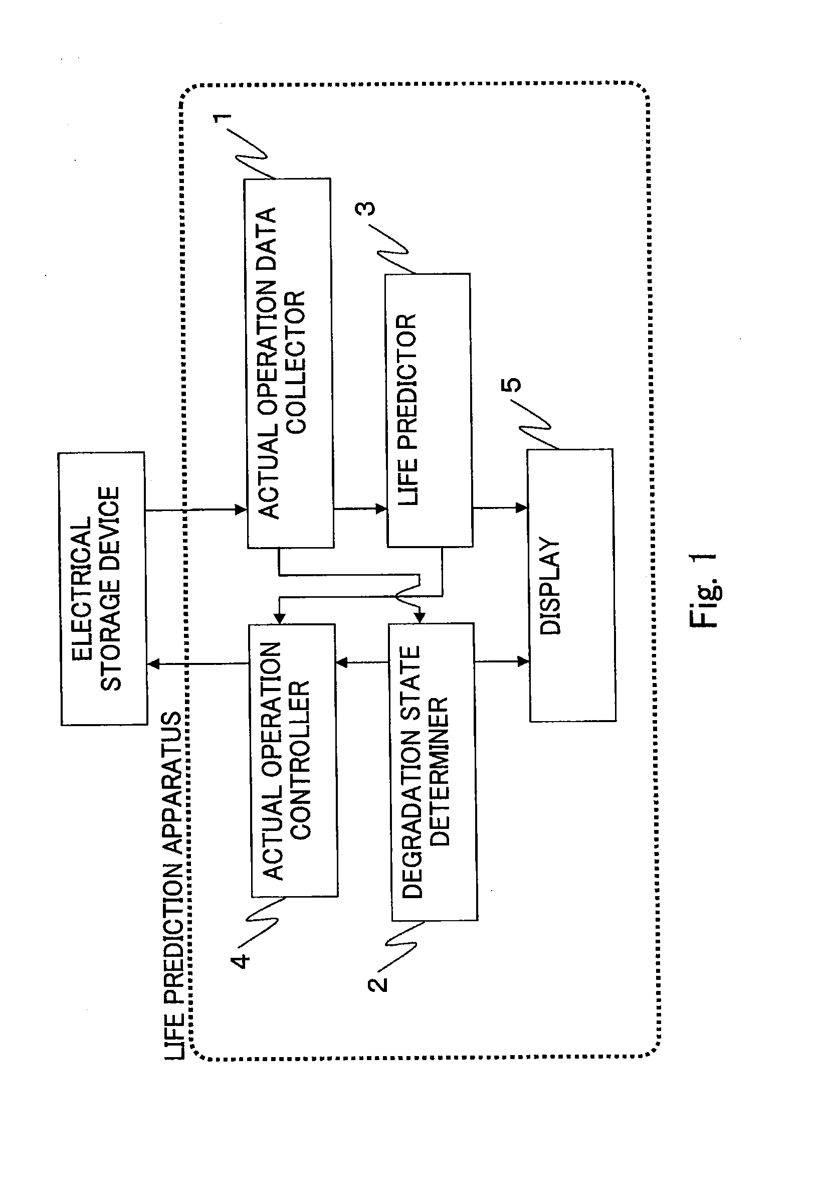
[0036]FIG. 1 is a configuration diagram of the life prediction apparatus for an electrical storage device according to Embodiment 1 of the present invention. The life prediction apparatus for an electrical storage device which is depicted in FIG. 1 is constituted by an actual operation data collector 1, a degradation state determiner 2, a life predictor 3, an actual operation controller 4, and a display 5.

[0037]In the present invention, the electrical storage device depicted in FIG. 1 is the object of life prediction. In the explanation below, a cylindrical lithium ion battery is assumed as the electrical storage device, but the electrical storage device in accordance with the present invention is not limited to the cylindrical lithium battery.

[0038]For example, a storage battery such as a lead storage battery, a nickel-cadmium battery, a nickel-hydride battery, a sodium-sulfur battery, and a redox flow battery, and an electrical storage device such as an electric double layer capac...

embodiment 2

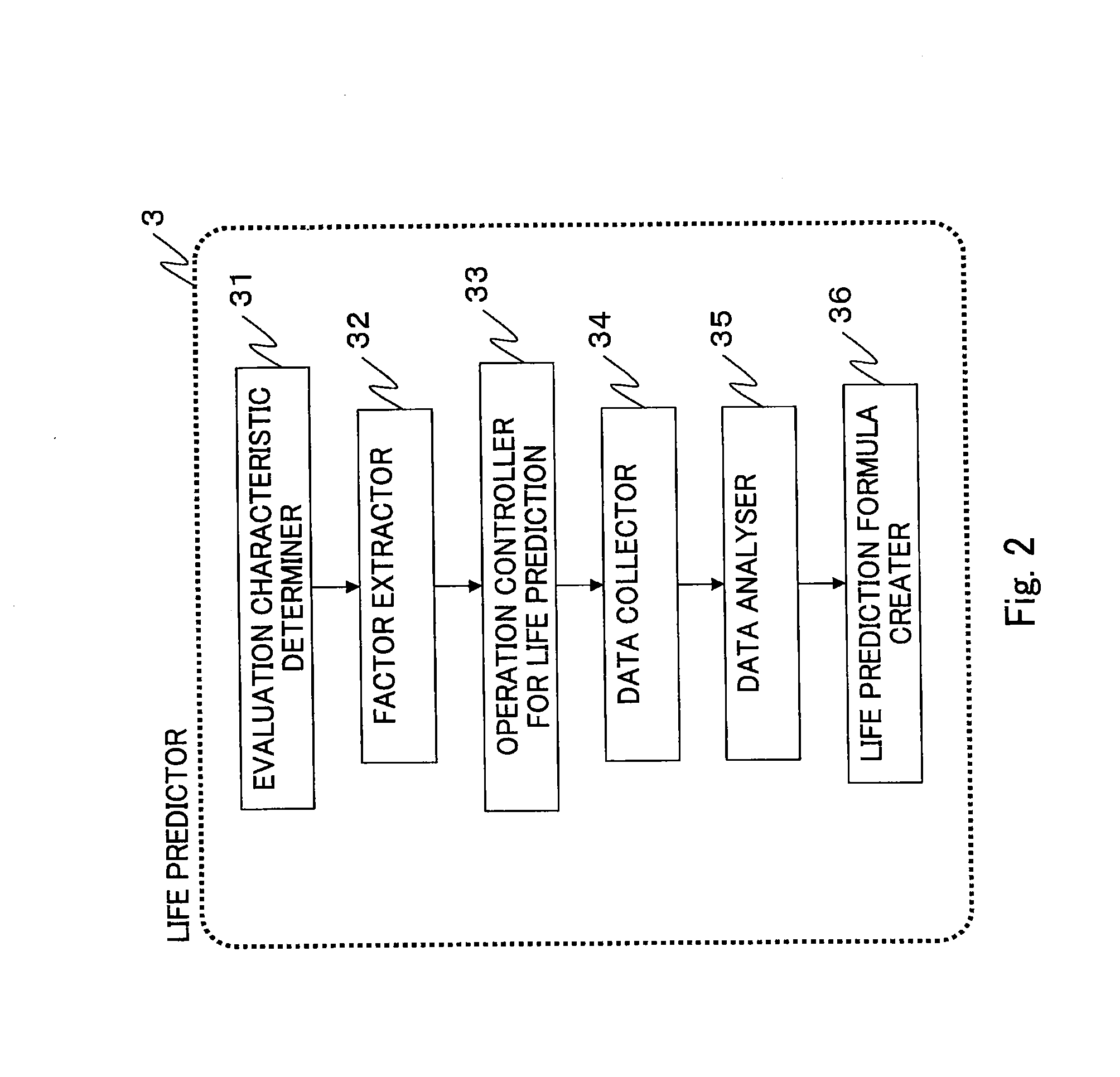
[0049]Embodiment 2 of the present invention is a specific embodiment of the life predictor 3 in Embodiment 1 described hereinabove.

[0050]FIG. 2 is a configuration diagram of the life predictor 3 in the life prediction apparatus for an electrical storage device according to Embodiment 2 of the present invention. The life predictor 3 depicted in FIG. 2 is constituted by an evaluation characteristic determiner 31, a factor extractor 32, an operation controller 33 for life prediction, a data collector 34, a data analyzer 35, and a life prediction formula creator 36.

[0051]FIG. 3 illustrates candidates for evaluation characteristics and factors in Embodiment 2 of the present invention. The evaluation characteristic as referred to herein is an estimated physical amount to be used in calculating the life of the electrical storage device which is the life prediction object, and the factor is an operation condition affecting the evaluation characteristic. For example, the evaluation character...

embodiment 3

[0101]In the case explained in Embodiment 3 of the present invention, the life prediction for random operation conditions is implemented offline, without the function of controlling the operation of the electrical storage device, by using the life prediction formula created on the basis of the accumulated measurement data which are based on the operation conditions in Embodiment 2.

[0102]FIG. 14 is a configuration diagram of the life prediction apparatus for an electrical storage device according to Embodiment 3 of the present invention. The life prediction apparatus depicted in FIG. 14 is constituted by an offline life predictor 3a, a display 5, and an operation condition input device 6.

[0103]In the life prediction apparatus for an electrical storage device depicted in FIG. 14, life prediction with respect to operation conditions can be implemented offline by setting a pre-calculated life prediction formula, without the function of controlling the operation of the electrical storage...


PUM


Abstract

A life prediction apparatus for an electrical storage device, which has a life predictor, includes: an operation controller for life prediction that controls operation of the electrical storage device; a data collector that collects measurement data with respect to a plurality of operation conditions and calculates and successively accumulates evaluation characteristics; a data analyzer that creates a regression formula representing a relationship between the evaluation characteristic and an operation time by curve fitting, with an appropriate approximation function, the accumulated evaluation characteristic data; and a life prediction formula creator that creates a life prediction formula for calculating a predicted value of the evaluation characteristic under random operation conditions on the basis of the regression formula.

Description

TECHNICAL FIELD[0001]The present invention relates to a life prediction apparatus for an electrical storage device and a life prediction method for an electrical storage device that can predict more accurately the life of the electrical storage device under random operation conditions by taking into account the type and operation conditions of the electrical storage device which affect the life of the electrical storage device.BACKGROUND ART[0002]Against the background of a low-carbon society, the types of electrical storage devices have diversified to include nickel-hydride batteries, lithium ion batteries, electric double layer capacitors, and the like. The application field of electrical storage devices has also expanded from the conventional portable devices to home appliances, backup power supplies, electric vehicles (EV), hybrid electric vehicles (HEV), and smart grids, and applications as large power supplies have demonstrated particularly significant expansion.[0003]Electric...

Claims


Application Information

Patent Timeline
Patent Type & Authority Applications(United States)
IPC IPC(8): G01R31/36
CPCG01R31/3679H01M10/48H01M10/42G01R31/367G01R31/392Y02E60/10H02J7/0048H02J7/005H02J7/00
Inventor KISE, MAKIKOMIKI, SHINSUKEYOSHIOKA, SHOJI
Owner MITSUBISHI ELECTRIC CORP
Why Eureka
Try Eureka