
Lens Moving Apparatus

a technology of moving apparatus and moving parts, which is applied in the direction of printers, instruments, cameras, etc., can solve the problems of narrow working space and increased time required for the connection process, and achieve the effect of facilitating the connection process, reducing the manufacturing price of the upper elastic member and the lower elastic member, and reducing the time required

Active Publication Date: 2015-11-12
LG INNOTEK CO LTD
View PDF4 Cites 35 Cited by
  • Summary
  • Abstract
  • Description
  • Claims
  • Application Information

AI Technical Summary

Benefits of technology

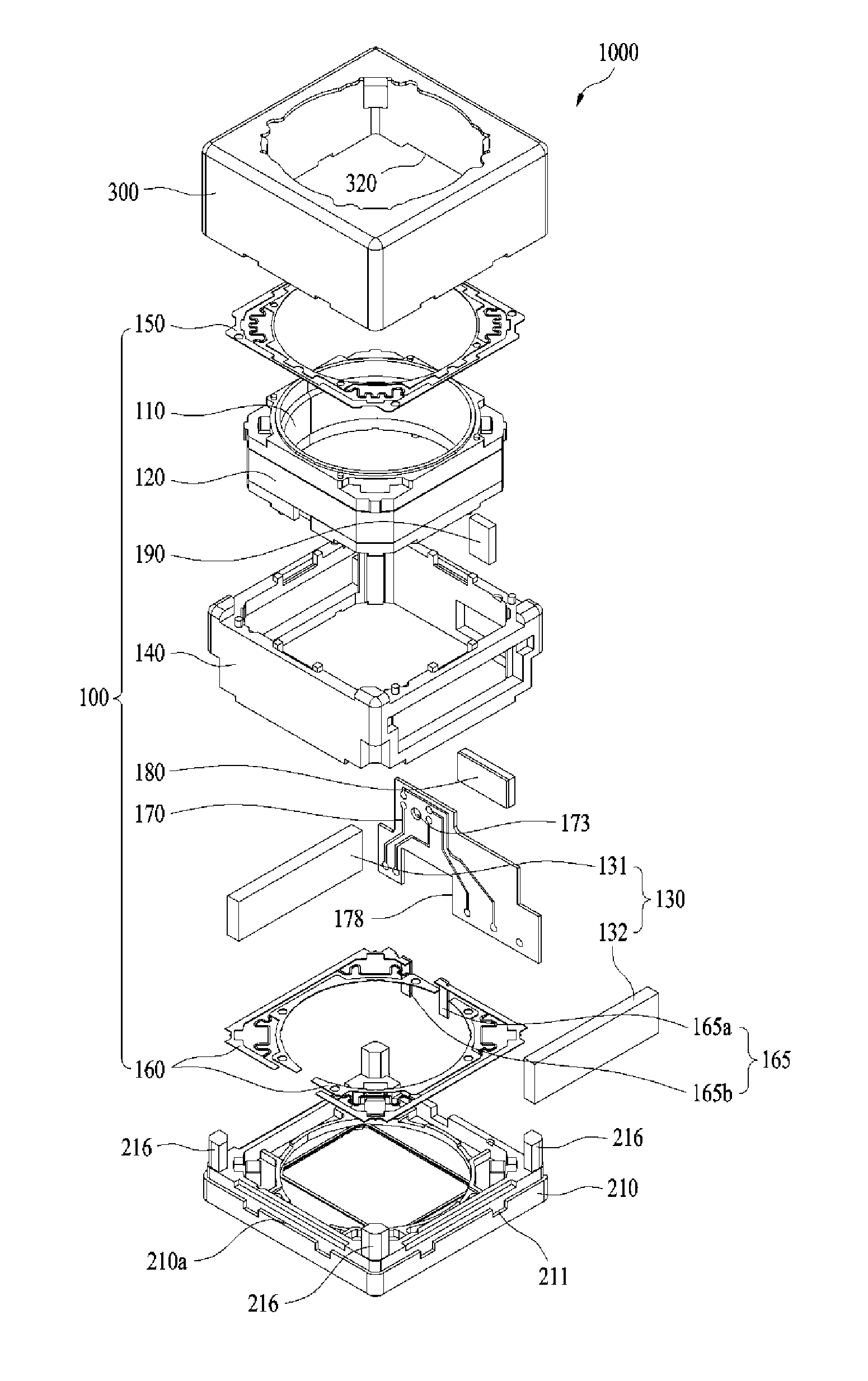
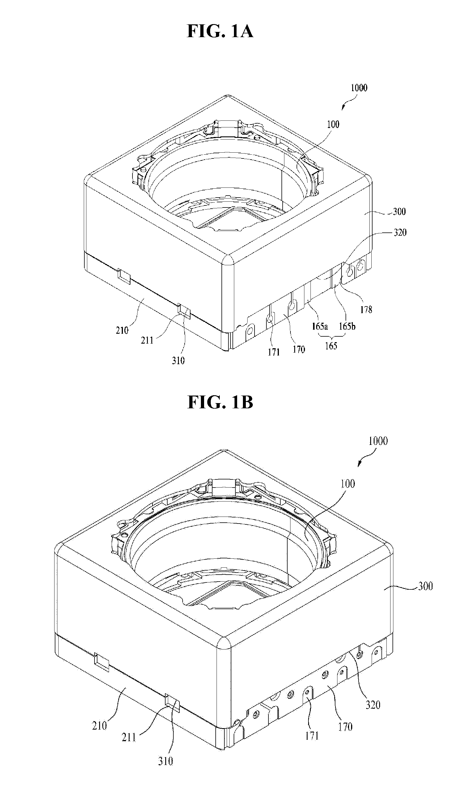
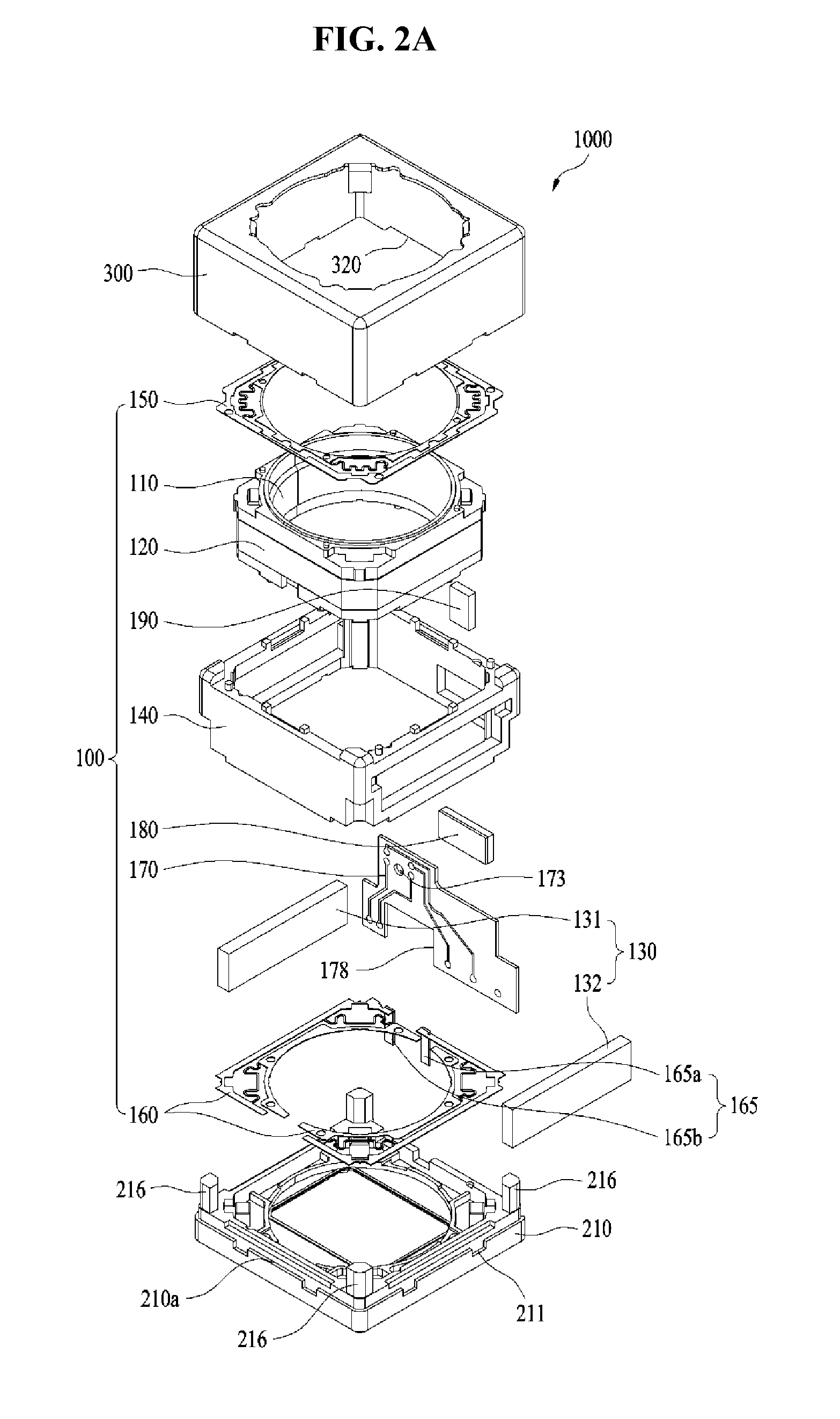
The present invention provides a lens moving apparatus that makes it easy to connect with an external power source, reducing the time required for the connection. Additionally, it creates a space for the connection between the lens moving apparatus and the external power source without increasing the manufacturing cost of the upper and lower elastic members.

Problems solved by technology

However, the conventional subminiature digital cameras require a great number of connection (e.g., soldering) points in order to receive power from an external power source.
In particular, in the conventional subminiature digital cameras, the great number of connection points is not concentrically arranged at a certain region, but distributed around the subminiature digital camera, which causes a worker difficulty in performing a connection process and causes an increased time required for the connection process.
In addition, the conventional subminiature digital cameras suffer from a narrow working space for connection (e.g., soldering) between a coil and an external power source in order to implement an auto-focus function.

Method used


Image

  • Lens Moving Apparatus
  • Lens Moving Apparatus
  • Lens Moving Apparatus

Examples


Embodiment Construction

[0038]Hereinafter, embodiments will be described with reference to the annexed drawings. In the drawings, the same or similar elements are denoted by the same reference numerals even though they are depicted in different drawings. In the following description, a detailed description of known functions and configurations incorporated herein will be omitted when it may make the subject matter of the disclosure rather unclear. Those skilled in the art will appreciated that some features in the drawings are exaggerated, reduced, or simplified for ease in description, and drawings and elements thereof are not shown always at the proper rate.

[0039]For reference, in the respective drawings, a rectangular coordinate system (x, y, z) may be used. In the drawings, the x-axis and the y-axis mean a plane perpendicular to an optical axis and, for convenience, an optical axis (z-axis) direction may be referred to as a first direction, an x-axis direction may be referred to as a second direction, ...


PUM


Abstract

Embodiments provide a lens moving apparatus including housing to support a driving magnet, a bobbin provided at an outer circumferential surface thereof with a coil located inside the driving magnet, the bobbin being moved in a first direction parallel to an optical axis within the housing via electromagnetic interaction between the driving magnet and the coil, a lower elastic member to connect a lower portion of the housing and a lower portion of the bobbin to each other, both ends of the coil being electrically connected to the lower elastic member, the lower elastic member having a first terminal electrically connected to an external power source so as to supply external power to the ends of the coil, and a printed circuit board provided at one side surface of the housing, the printed circuit board having a second terminal electrically connected to the external power source.

Description

CROSS REFERENCE TO RELATED APPLICATIONS[0001]This application claims the benefit under 35 U.S.C. §119 of Korean Patent Application Nos. 10-2014-0055361 and 10-2014-0055363, filed May 9, 2014, which are herein incorporated by reference in their entirety.TECHNICAL FIELD[0002]Embodiments relate to a lens moving apparatus and, more particularly, to a lens moving apparatus which may improve space efficiency of a bobbin and reduce focusing time of a lens via feedback of a displacement of the lens in the optical axis direction.BACKGROUND[0003]In recent years, IT products equipped with subminiature digital cameras such as, for example, cellular phones, smartphones, tablet PCs, and notebook computers, have actively been developed.[0004]IT products equipped with conventional subminiature digital cameras incorporate a lens moving apparatus for aligning the focal distance of a lens by adjusting a distance between the lens and an image sensor that converts outside light into a digital image.[000...

Claims


Application Information

Patent Timeline
Patent Type & Authority Applications(United States)
IPC IPC(8): G02B7/04G03B3/10
CPCG03B3/10G02B7/04G02B7/08G03B30/00G03B2205/0069H04N23/51H04N23/57H04N23/55H04N23/54G03B5/00G03B2205/0015G02B7/09G03B13/36
Inventor LEE, JUN TAEKPARK, SANG OKSON, BYUNG WOOKLEE, SEONG MIN
Owner LG INNOTEK CO LTD
Learn More