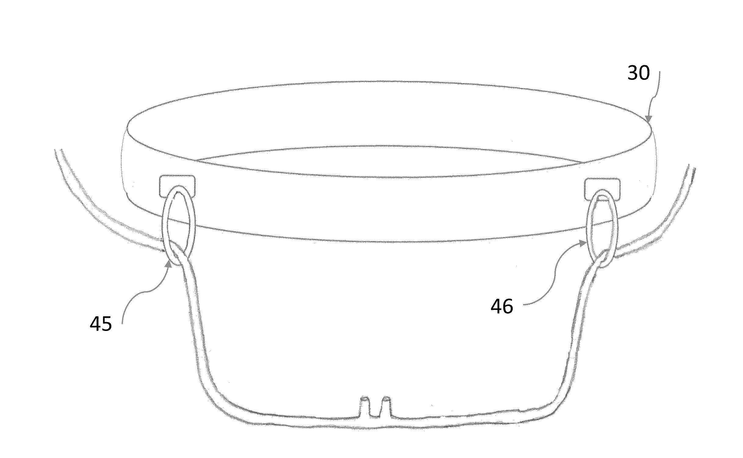
[0019]The present invention is an eyeglass and medical device retainer comprising an adjustable head band, and at least one loop element that wraps around the eyeglasses or medical device being used by the wearer and thereby maintaining the eyeglasses or medical device in the desired position on the wearer's head.
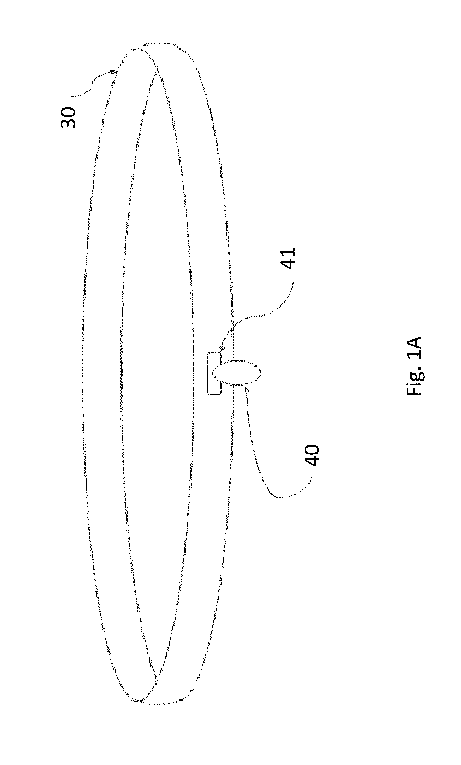
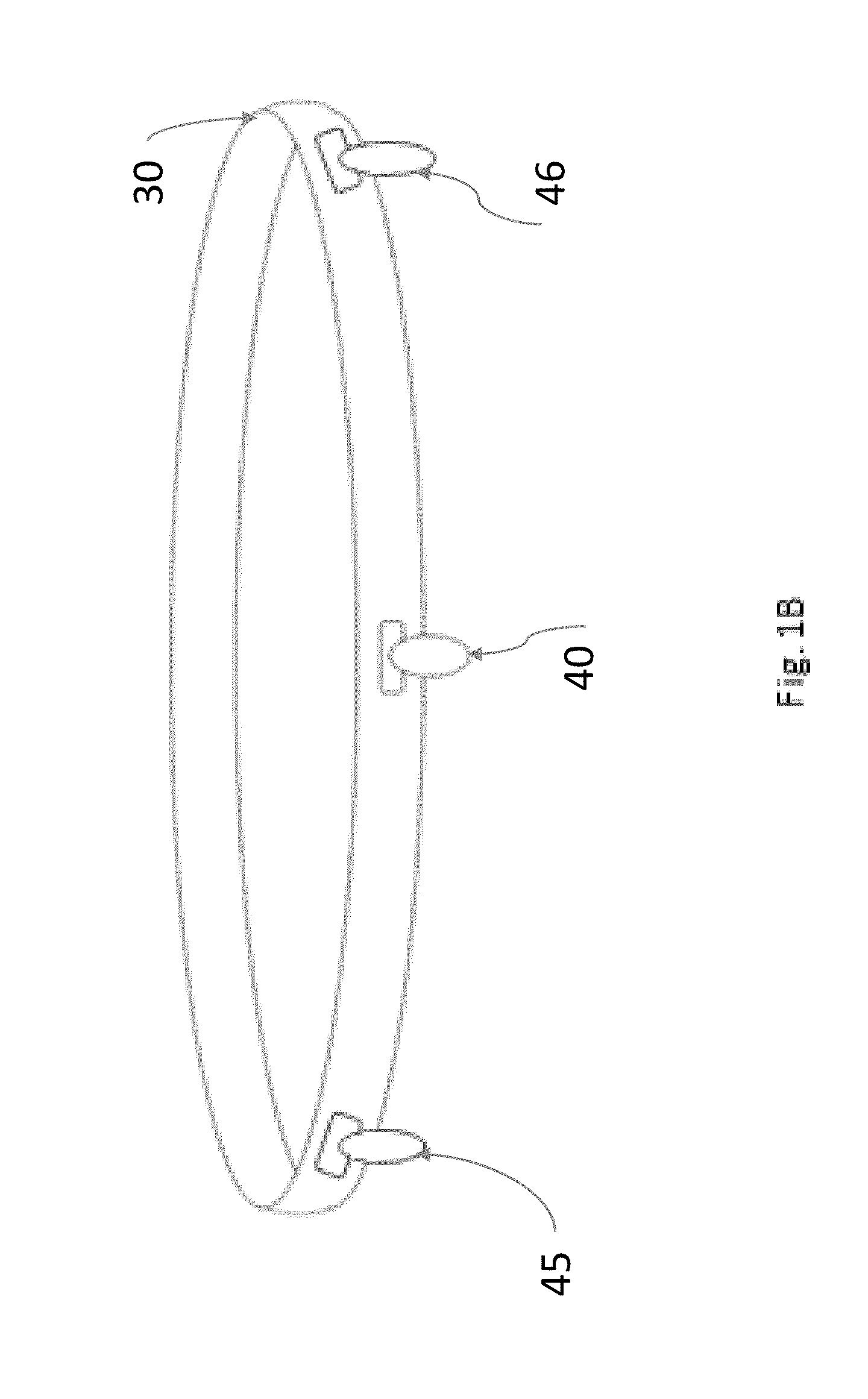
[0020]In more particularity, as shown in FIG. 1A, the eyeglass retainer comprises a textile head band 30 with a loop 40. The textile head band 30 is designed to encircle the wearer's head above the wearer's ears and along the forehead area of the wearer. The loop 40 has two ends such that one end is affixed to the head band 30 and the other end is removably attachable to the head band 30. As shown in use, the wearer can use the loop 40 to encircle the center section of the eyeglasses or sun glasses, and then put the head band 30 on along with the eyeglasses or sun glasses. With the user wearing the head band, his or her glasses will be held in position, and will not slide down the wearer's nose due to moisture, sweat, or simply movement.
[0021]The second end of the loop may be attached to the head band 30 by means of a snap mechanism, or a button 41. Allowing for complete variability with respect to the position of the glasses on the wearer's head, an alternative means for attaching the loop 40 is through a hook and loop textile, use as Velcro®.
[0022]The head band 30 can be manufactured from an elastic textile, such as Lycra®, allowing for variation in size to account for differing circumference dimensions for differing users. Alternatively, the head band 30 can be manufactured with two ends having attachment means at each end. By way of example, the two ends could have respective snaps elements, or a button and hole, or similar to the loop attachment described above, the ends of the head band 30 could have respective hook and loop elements to allow full variability in sizing the head band to the wearer.
[0023]In an alternative embodiment of the head band eyeglass holder, FIG. 1B shows head band 30 having a plurality of loop elements 40, 45, 46. As shown, in this embodiment, one loop element 40 can be located in the approximate center of the head band 30, to loop around the center nose piece of the wearer's glasses, and other loop elements 45, 46 can be located on approximate opposite sides of the head band 30, to loop around the respective ear pieces of the wearer's glasses. The loop attachment means for this embodiment can include the same type of connections as described above for the FIG. 1A embodiment, including snaps, buttons, or a textile hook and loop material. The FIG. 1B embodiment provides additional retention and holding points as compared to the FIG. 1A embodiment, and accordingly, will hold the wearer's glasses in position more robustly.
[0024]As a head band which may be used by athletes or other workers, the head band 30 can be made of a moisture absorbing material thereby eliminating sweat from getting into the wearer's eyes, or running onto the wearer's glasses. Such head band 30 material should be washable to allow the wearer to keep the device clean. One example of such material could be a terry cloth type material.
[0025]The head band/loop device can, in another preferred embodiment be used by medical patients to hold certain medical devices in place near or on the patient's head. By way of one example, as illustrated in FIG. 2, the head band 30 can be manufactured with a plurality of loops 45, 46 placed along the sides of the head band 30. In such locations, the loops can hold oxygen tubes that need to be held in place near the patient's nostril. Although two loops 45, 46 are shown in FIG. 2, further loops could be used to further hold the oxygen tubes in place. While tape is most often used to hold such tubes in place, the adhesive side of the tape will often cause discomfort to the patient, especially when the tape is to be removed from the patient's head. Where the oxygen tubes are moved or replaced repeatedly, the skin abrasion and discomfort to the patient with repeated removal and replacement of the tape, is only increased and made worse. The head band/loop device as illustrated in FIG. 2 provides a ready solution to this problem.
[0026]Similar to the eyeglass retainer embodiment, the medical device holder embodiment may have the head band 30 manufactured from an elastic material, or it may be made with two ends allowing for variable sizing for different patients. For the medical embodiment, the head band 30 materials can be manufactured of a sterile material, especially if the patient may have abrasions or wounds in the general area where the head band 30 encircles the patient's head. Whether the head band 30 is manufactured from a sterile material, or some other textile, for the medical embodiment, the head band/medical device holder should be disposable after each use.
[0027]In view of the placement of the head band 30 around a patient's forehead and temple region, in a further preferred embodiment to provide added medical assistance and information to caregivers, temperature sensors 90 can be incorporated along the inside of the head band 30, as illustrated in FIG. 3. Using a plurality of temperature sensors 90 allows for multiple readings to enhance accuracy of the measurement. The temperature sensors 90 could be directly connected to a display incorporated into the head band 30 (as shown in FIG. 3), or the sensors 90 could transmit the temperature data to a transmitter 91 built into the head band 30, which sends a wireless signal to one or more recipients, thereby providing the patient's temperature without the need to disturb the patient during rest.
[0028]A further enhancement to the medical embodiment of the head band 30 includes, as shown in FIG. 4, a pulse monitor 93 incorporated into the inside of the head band 30 near the temple regions of the patient. Using dual pulse monitors 93 provides some redundancy by reading the patient's pulse at both the left and right hand sides of the patient's head. The pulse monitors 93 provide real-time data to a transmitter 95 embedded into the head band 30. Similar to the above temperature sensor embodiment, the transmitter 95 sends a wireless signal to one or more recipients, which could include a digital or graphical readout in proximity to the patient. Through use of the medical head band 30, caregivers and medical technicians can monitor in real-time the pulse of a patient without further disturbing the patient who may be sleeping or otherwise resting.
[0029]In still a further enhancement to the medical head band device, to monitor for falls or rapid movements of the patient, especially for older patients, at least one accelerometer 97 can be incorporated into the head band 30, as illustrated in FIG. 5. Similar to the FIG. 4 preferred embodiment, the accelerometer, or plurality of accelerometers 97 is connected to a transmitter 95 that can send a wireless signal to one or more recipients. The accelerometers 97 measure rapid movements of the patient's head, and accordingly monitors if the patient were to fall or had a seizure. A plurality of accelerometers can be used for redundancy and also for consistency of sensed accelerations to alleviate potential false alarms should a single accelerometer inadvertently sense a fall. The recipient or recipients of the wireless accelerometer signal could be nurse's station or, if in a hospital setting, a bedside aural alarm.
[0030]While various preferred embodiments have been disclosed herein showing use of an eyeglass head band retainer, and a medical device head band retainer, in another preferred embodiments, the head band device could be used to hold other apparatus in position on a wearer's head, or to monitor other medical data of a patient.
[0031]The above detailed description teaches certain preferred embodiments for the present inventive eyeglass and medical device retainer using a head band and loop elements. While preferred embodiments have been described and disclosed, it will be recognized by those skilled in the art that modifications and/or substitutions are possible and such modifications and substitutions are within the true scope and spirit of the present invention. It is likewise understood that the attached claims are intended to cover all such modifications and/or substitutions.