Ejector

a technology of ejector and nozzle, which is applied in the direction of machines/engines, refrigeration components, light and heating apparatus, etc., can solve the problems of unsatisfactory pressurizing of refrigerant unsatisfactory refrigerant pressure by the diffuser portion, and unsatisfactory refrigerant pressure in the body of the ejector, etc., to achieve high energy conversion efficiency, reduce the amount of refriger

Inactive Publication Date: 2015-11-19
DENSO CORP
View PDF43 Cites 4 Cited by
  • Summary
  • Abstract
  • Description
  • Claims
  • Application Information

AI Technical Summary

Benefits of technology

[0027]In other words, the configuration that does not reduce the velocity of the refrigerant flowing through the diffuser passage in the swirling direction can be easily realized as the configuration in which the driving force is transmitted from the driving device to the nozzle body. Therefore, a reduction in the spiral refrigerant flow channel for pressurizing the refrigerant in the diffuser passage is restricted, thereby being capable of suppressing a reduction in the pressurizing amount of refrigerant in the diffuser passage.
[0028]This makes it possible to provide the ejector capable of achieving a high energy conversion efficiency (corresponding to the nozzle efficiency) in the nozzle passage, and also achieving a high pressurizing performance in the diffuser passage, regardless of load variations of a refrigeration cycle device without upsizing the body.
[0029]Further, the refrigerant flowing in the diffuser passage may swirl in the same direction as that of the refrigerant swirling in the swirling space. The spiral refrigerant flow channel for pressurizing the refrigerant in the diffuser passage is effectively restrained from being shortened, thereby being capable of effectively suppressing a reduction in the pressurizing amount of the refrigerant in the diffuser passage.

Problems solved by technology

In this case, the nozzle efficiency by causing the gas-liquid two phase refrigerant to flow in the second nozzle is not improved.
As a result, the refrigerant may not be sufficiently pressurized by the diffuser portion.
However, when the diffuser portion of this type is applied, a length of the nozzle portion in the axial direction becomes longer as a whole of the ejector, resulting in a risk that a body of the ejector becomes unnecessarily longer in the normal load of the ejector refrigeration cycle.

Method used


Image

  • Ejector
  • Ejector
  • Ejector

Examples


first embodiment

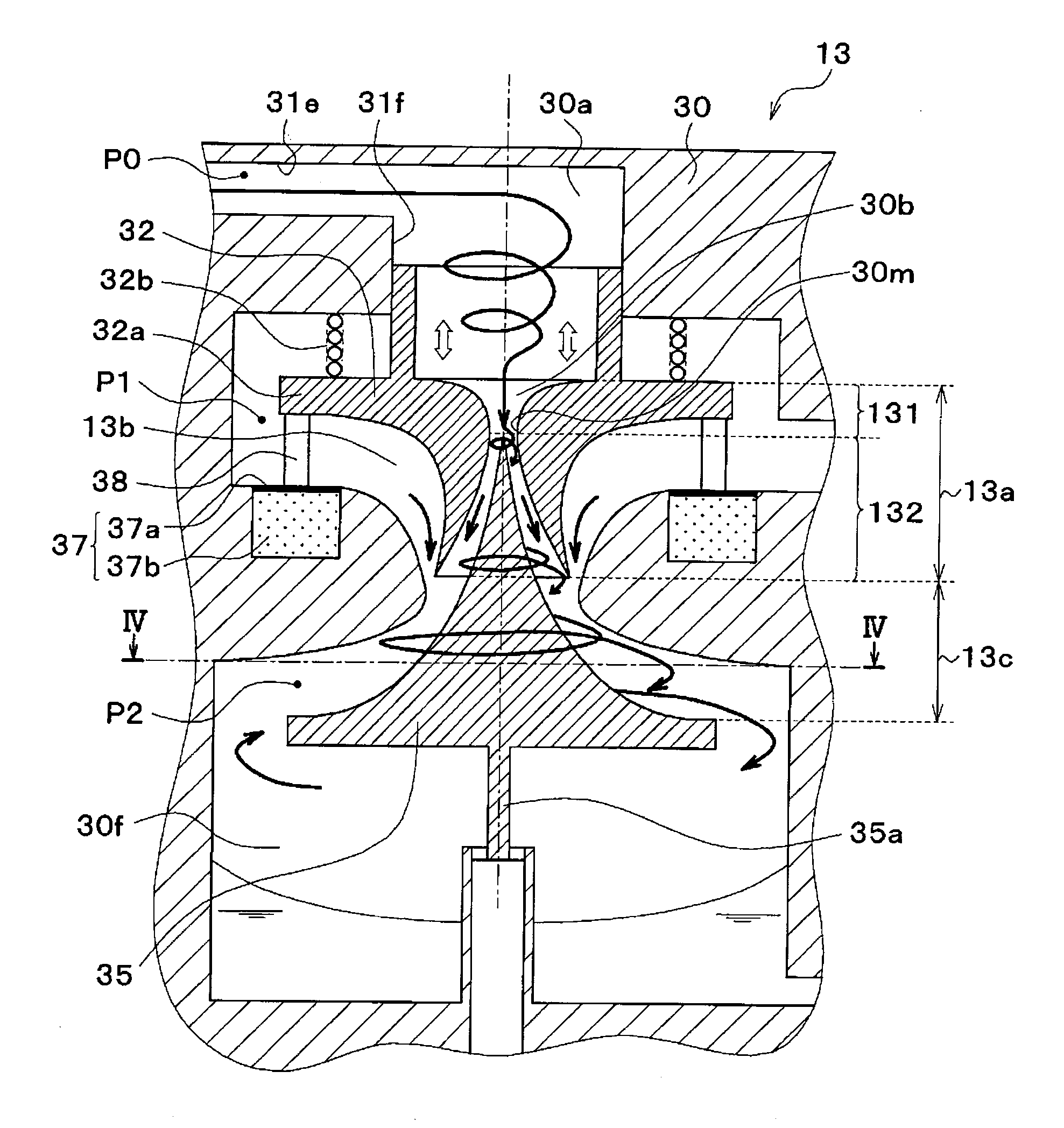
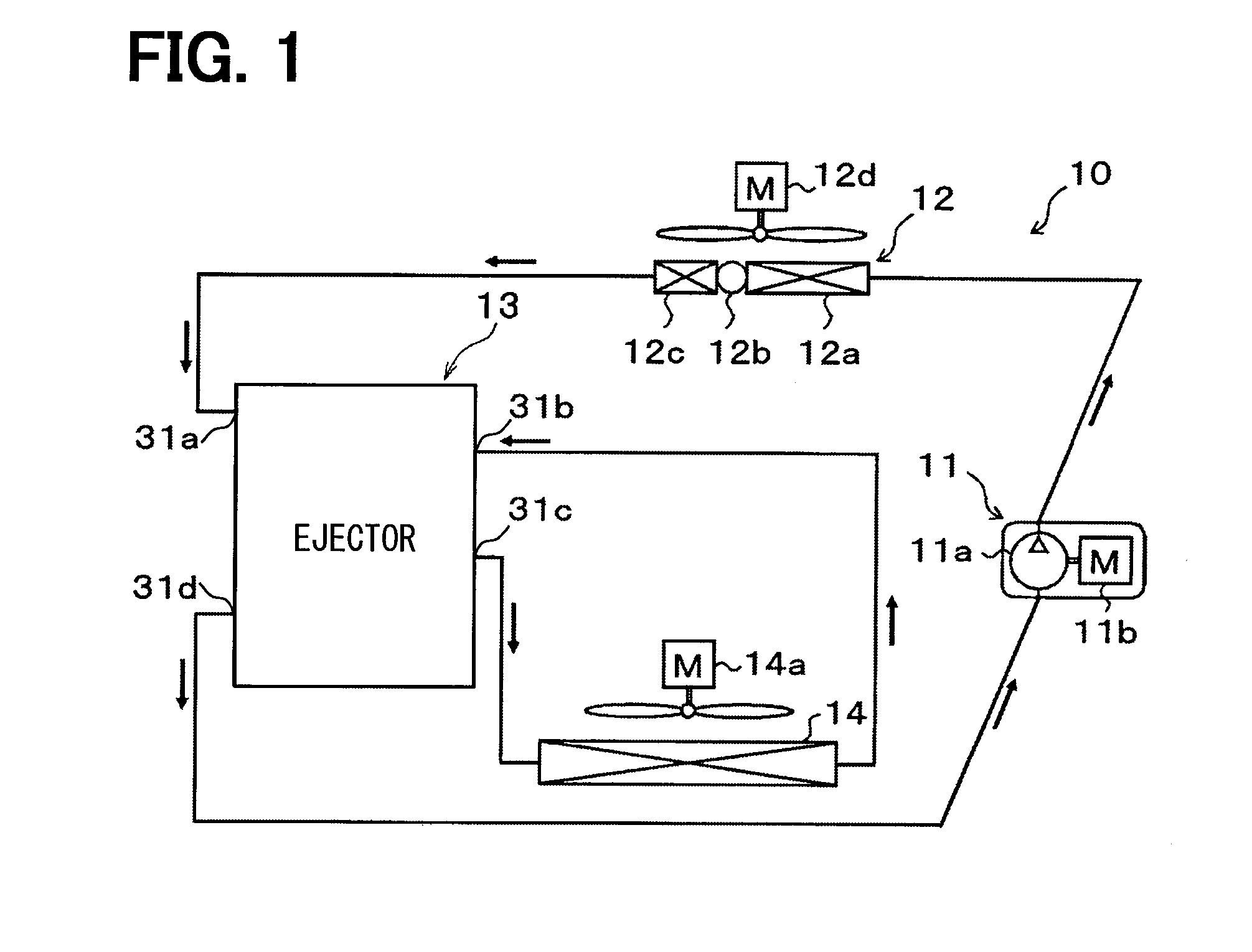
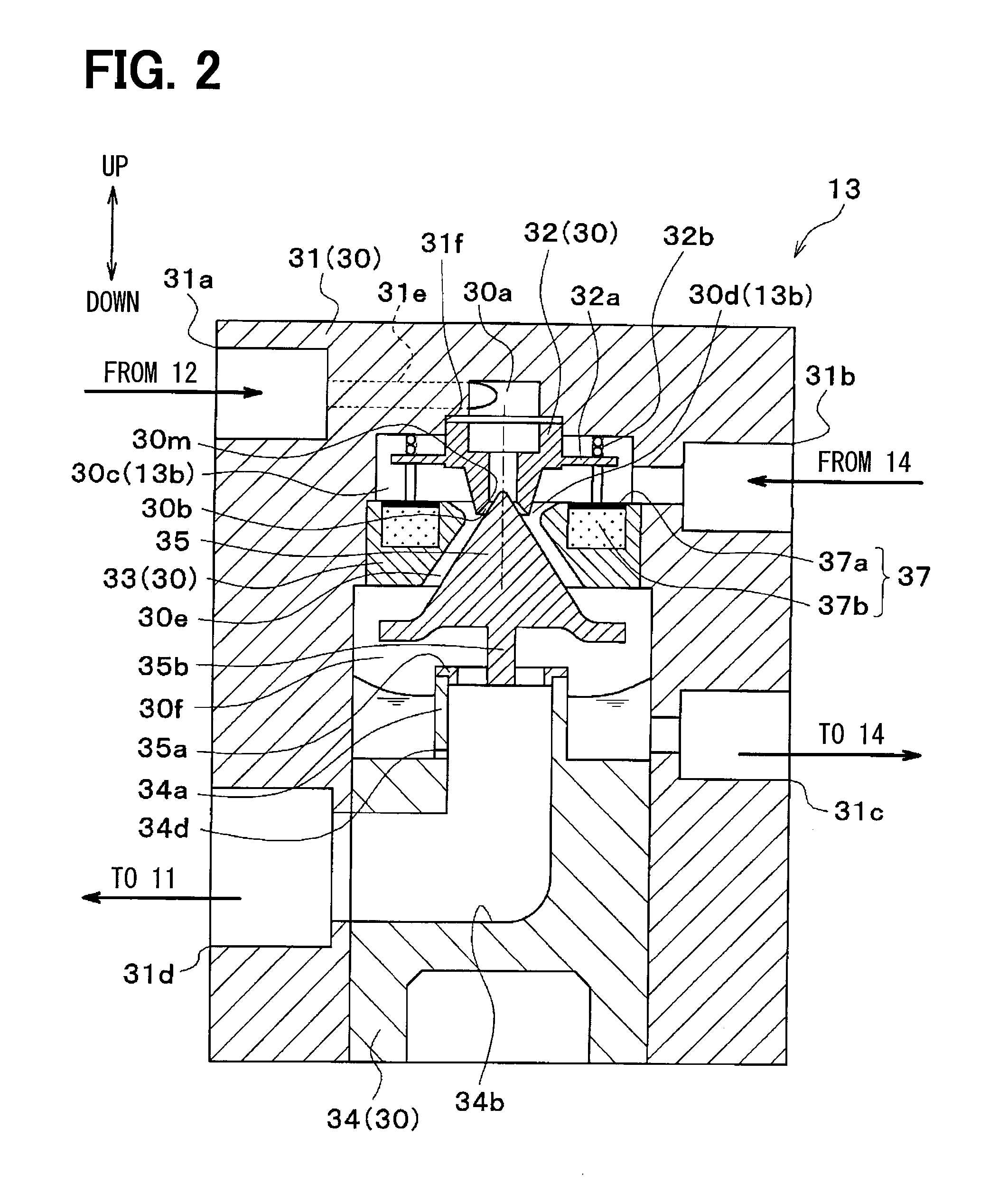
[0042]A first embodiment of the present disclosure will be described with reference to FIGS. 1 to 5. As illustrated in FIG. 1, an ejector 13 according to this embodiment is applied to a refrigeration cycle device having an ejector as refrigerant depressurizing means, that is, an ejector refrigeration cycle 10. Moreover, the ejector refrigeration cycle 10 is applied to a vehicle air conditioning apparatus, and performs a function of cooling blast air which is blown into a vehicle interior that is a space to be air-conditioned.

[0043]First, in the ejector refrigeration cycle 10, a compressor 11 draws a refrigerant, pressurizes the refrigerant to a high pressure refrigerant, and discharges the refrigerant. Specifically, the compressor 11 of this embodiment is an electric compressor in which a fixed-capacity compression mechanism 11a and an electric motor 11b for driving the compression mechanism 11a are accommodated in a single housing.

[0044]Various compression mechanisms, such as a scr...

second embodiment

[0127]In this embodiment, a description will be given of an example in which the arrangement mode of the driving device 37 is changed as illustrated in FIG. 6 in the first embodiment. Meanwhile, FIG. 6 is a cross-sectional view corresponding to FIG. 2 in the first embodiment, and the same portions as or the equivalent portions to the portions of the first embodiment are denoted by the same reference numerals.

[0128]Specifically, the driving device 37 according to this embodiment is arranged inside of an auxiliary plate 36 (fixed plate). The auxiliary plate 36 is formed of a disc-shaped member made of metal that is provided with a columnar through-hole which penetrates through both sides thereof in the center portion. The auxiliary plate 36 accommodates therein a driving device 37 having the same configuration as that in the first embodiment on a radially outer side of the through-hole.

[0129]A center axis of the through-hole in the auxiliary plate 36 is arranged coaxially with the cen...


PUM


Abstract

An ejector includes a body part having a depressurizing space in which a refrigerant flowing out of a swirling space is depressurized, a suction passage that draws a refrigerant from an external, and a pressurizing space in which the refrigerant from the depressurizing space is mixed with the refrigerant from the suction passage, a conical passage formation member that is arranged in the body part, and a driving device that displaces a nozzle body of the body part forming the depressurizing space. A nozzle passage is defined on an outer peripheral side of the passage formation member in the depressurizing space, a diffuser passage is formed on an outer peripheral side of the passage formation member in the pressurizing space, and an actuating bar that couples the driving device with the nozzle body is arranged without crossing the diffuser passage.

Description

CROSS REFERENCE TO RELATED APPLICATION[0001]This application is based on and incorporates herein by reference Japanese Patent Applications No. 2012-272099 filed on Dec. 13, 2012, and No. 2013-219043 filed on Oct. 22, 2013.TECHNICAL FIELD[0002]The present disclosure relates to an ejector that depressurizes a fluid, and draws the fluid by a suction action of an ejection fluid ejected at high speed.BACKGROUND ART[0003]Conventionally, an ejector has been known as a depressurizing device applied to a vapor compression refrigeration cycle device. The ejector of this type has a nozzle portion that depressurizes refrigerant, draws a gas-phase refrigerant which has flowed out of an evaporator due to a suction action of an ejection refrigerant ejected from the nozzle portion, mixes the ejection refrigerant with the suction refrigerant in a pressure increase part (diffuser portion), thereby being capable of increasing the pressure.[0004]Therefore, in the refrigeration cycle device having the e...

Claims


Application Information

Patent Timeline
Patent Type & Authority Applications(United States)
IPC IPC(8): F25B1/06F25B41/06F04F5/04F25B9/08
CPCF25B1/06F04F5/04F25B41/06F25B9/08F25B41/00F25B2341/001F25B2341/0012F04F5/461
Inventor SUZUKI, TATSUHIRONISHIJIMA, HARUYUKIYAMADA, ETSUHISA
Owner DENSO CORP
Why Eureka
Try Eureka