Method for forming a pressed component, method for manufacturing a pressed component, and die apparatus for forming a pressed component

a technology of pressed components and dies, which is applied in the field of forming components, pressed components, and die apparatus for forming components, which can solve the problems of large equipment including die apparatus, large equipment complexity, and many restrictions on the shape of the boss portion of the pressed component, so as to achieve the effect of easy formation

Inactive Publication Date: 2015-11-26
FCC KK
View PDF7 Cites 6 Cited by
  • Summary
  • Abstract
  • Description
  • Claims
  • Application Information

AI Technical Summary

Benefits of technology

[0011]According to the second feature of the present invention, in the preliminary boss portion-forming step, the projecting end portion of the preliminary boss portion is formed so as to have a thickness of less than or equal to one tenth the thickness of the blank. Therefore, a rough hole having a diameter smaller than the thickness of the plate member can be easily formed in the rough hole-forming step.

Problems solved by technology

Accordingly, the conventional method involves the problem that equipment including a die apparatus becomes large and complex.
In particular, in the case of forming a female thread on the inner circumference of the boss portion of the pressed component by tapping, the problem arises that the greater the degree to which the wall thickness of the boss portion is increased so as to increase the rigidity of the female thread, the greater the difficulty in forming the boss portion by a press.
The above-described conventional method for forming a pressed component has another problem that many restrictions are imposed on the shape of the boss portion of the pressed component.
Specifically, in the conventional method for forming a pressed component, the entirety of the closed portion of the preform portion becomes scrap as a result of formation of a rough hole by piercing, and material is not used efficiently.
In addition, in a piercing process to form a through-hole in a material, it is generally impossible to form a through-hole having a diameter smaller than the thickness of the plate material.
Thus, the conventional method for forming a pressed component has the problem that the inner diameter of the boss portion is restricted to one greater than the thickness of the blank.

Method used


Image

  • Method for forming a pressed component, method for manufacturing a pressed component, and die apparatus for forming a pressed component
  • Method for forming a pressed component, method for manufacturing a pressed component, and die apparatus for forming a pressed component
  • Method for forming a pressed component, method for manufacturing a pressed component, and die apparatus for forming a pressed component

Examples


Embodiment Construction

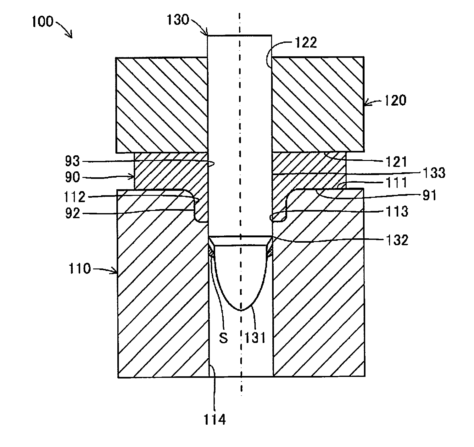
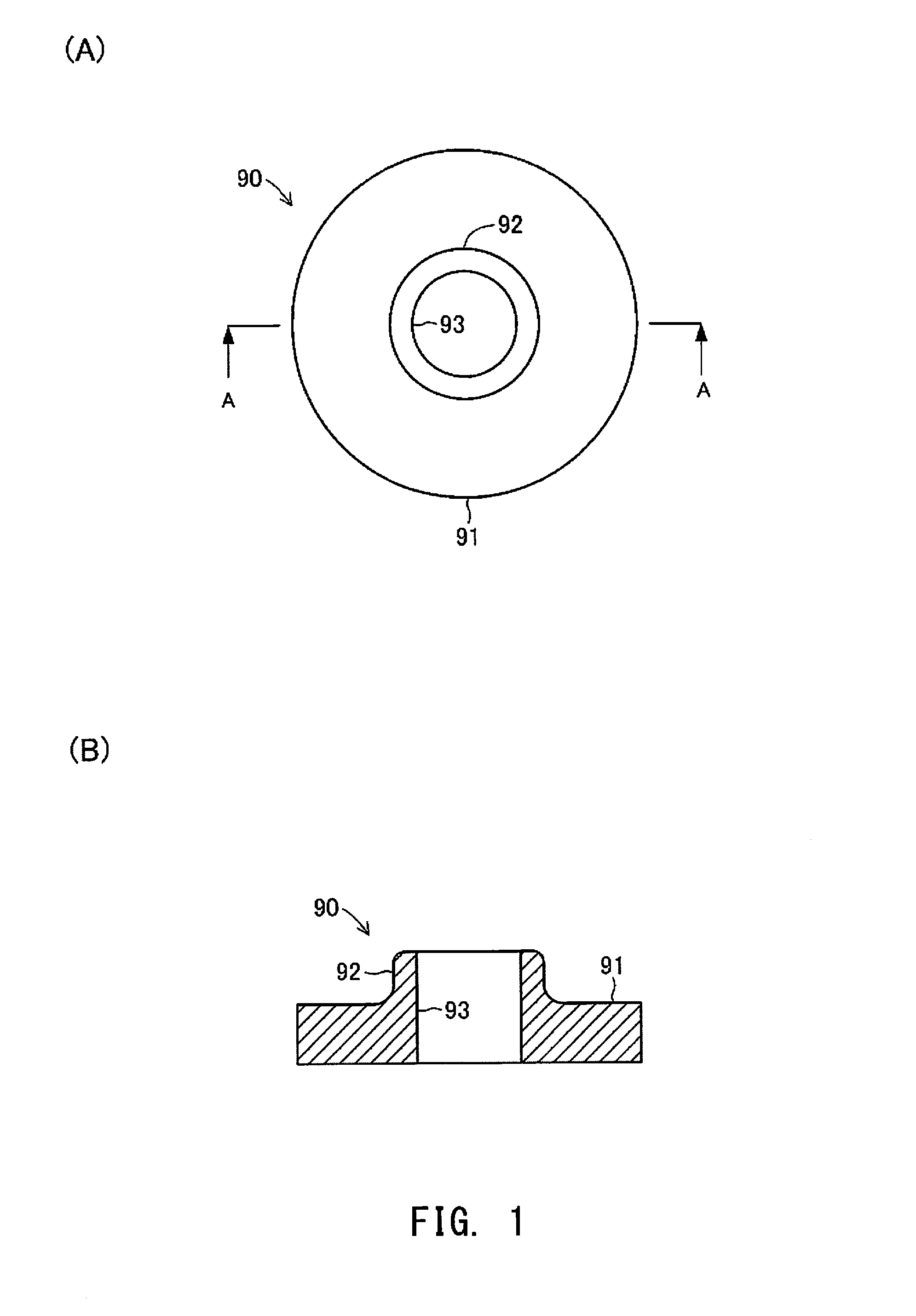
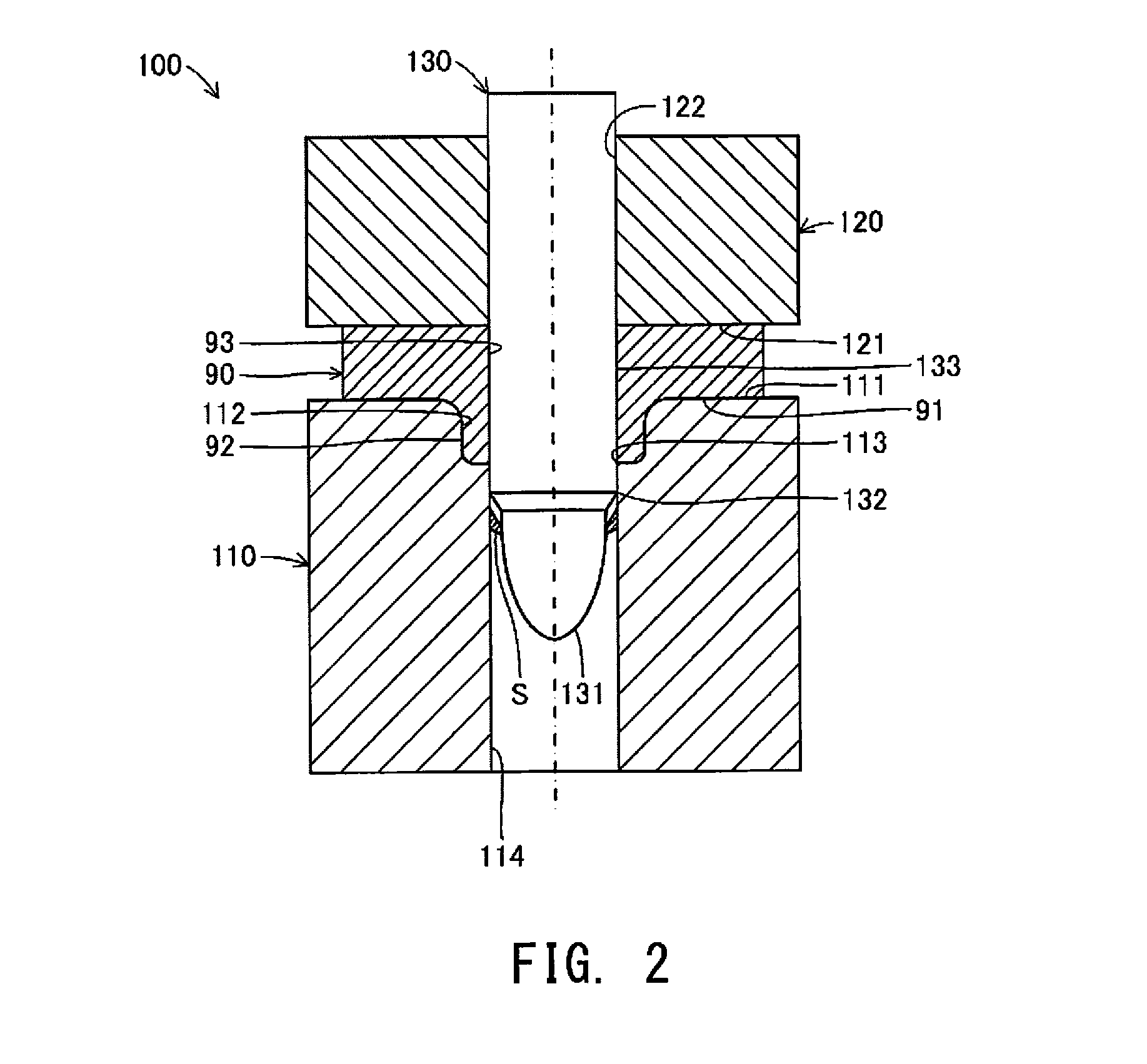
[0022]A pressed component-forming method according to one embodiment of the present invention will be described below with reference to the drawings. FIGS. 1(A) and 1(B) schematically illustrate the structure of a pressed component 90 formed by a pressed component-forming method of the present invention. FIG. 1(A) is a plan view of the pressed component 90, and FIG. 1(B) is a cross-sectional view of the pressed component 90 taken along line A-A in FIG. 1(A). FIG. 2 is a cross-sectional view schematically showing how the pressed component 90 is formed by the pressed component-forming method of the present invention. The figures referred to in the description are schematically illustrated with some components exaggerated in order to facilitate an understanding of the present invention. Therefore, components shown in the drawings may have dimensions, proportions, etc. which are different from the actual ones.

[0023]The pressed component 90 formed by a pressed component-forming method ac...


PUM

PropertyMeasurementUnit
thicknessaaaaaaaaaa
thicknessaaaaaaaaaa
diameteraaaaaaaaaa

Abstract

The present invention provides a method for forming a pressed metal component, a method for manufacturing such a pressed component, and a die apparatus for forming such a pressed component which decrease the size and the degree of complexity of equipment used for forming a pressed metal component having a plate-shaped base portion and a tubular boss portion extending from the base portion and allow formation of the boss portion in a wide variety of shapes. A piercing die 110, a holding body 120, and a piercing punch 130 are used to form a pressed component 90. The piercing die 110 has a receiving portion 111, an outer shape-forming portion 112, and a die-side cutting edge 113. The piercing punch 130 has an inner shape-forming portion 131, a punch-side cutting edge 132, and a straight portion 133. In a process of forming the pressed component 90, the piercing punch 130 is pressed against a preform 90′ formed from a blank BL and having a preliminary boss portion 92′ so as to cause part of the preliminary boss portion 92′ to flow toward the outer shape-forming portion 112, and so as to then cut off another part of the preliminary boss portion 92′ to thereby form a boss portion 92.

Description

TECHNICAL FIELD[0001]The present invention relates to a method for forming a pressed metal component having a plate-shaped base portion and a tubular boss portion extending from the base portion, a method for manufacturing such a pressed component, and a die apparatus for forming such a pressed component.BACKGROUND ART[0002]In the assembly of what are referred to as machine parts for machinery, a pressed metal component having a plate-shaped base portion and a tubular boss portion extending from the base portion has conventionally been used. A pressed component is generally formed by drawing, stretch flanging, blanking, and cutting.[0003]For example, below-described Patent Document 1 discloses a method for forming a pressed component which includes forming a tubular preform portion on a plate-shaped blank such that the preform portion protrudes from the blank and has a closed central portion, and removing the closed central portion of the preform portion by piercing to form a tubula...

Claims


Application Information

Patent Timeline
Patent Type & Authority Applications(United States)
IPC IPC(8): B21D28/24B21D28/14B21D19/08
CPCB21D28/243B21D28/14B21D19/08B21D19/088B21J5/10B21D28/26B21D28/34
Inventor KAWAI, KEITAROSHIMIZU, YUKI
Owner FCC KK
Why Eureka
Try Eureka