Turbine engine assemblies

a technology of turbine engine and engine body, which is applied in the field of aircraft systems, can solve the problems of low engine system efficiency

Inactive Publication Date: 2015-11-26
GENERAL ELECTRIC CO
View PDF10 Cites 86 Cited by
  • Summary
  • Abstract
  • Description
  • Claims
  • Application Information

AI Technical Summary

Problems solved by technology

Use of compressor air for cooling may lower efficiency of the engine system.

Method used


Image

  • Turbine engine assemblies
  • Turbine engine assemblies
  • Turbine engine assemblies

Examples


Embodiment Construction

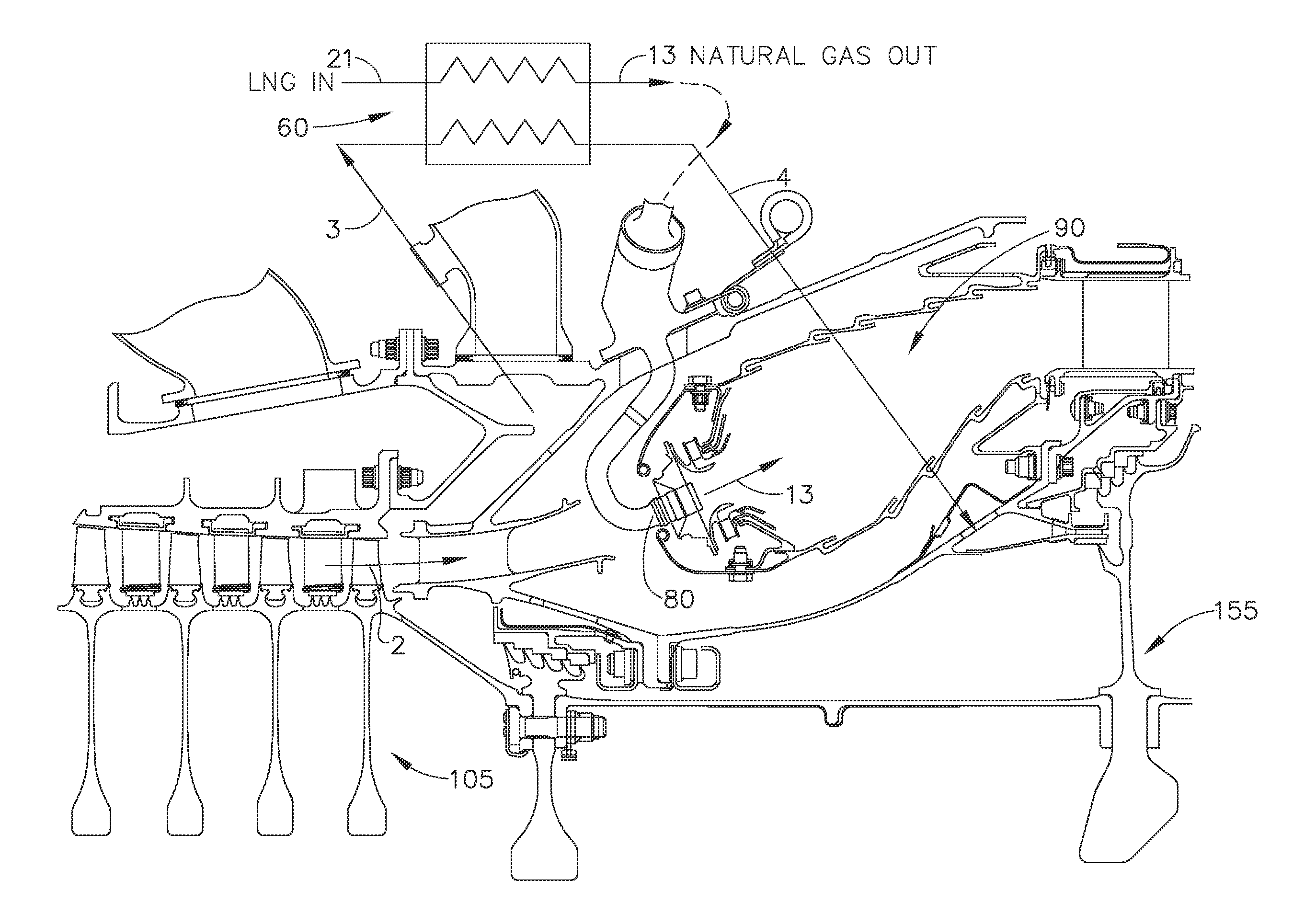
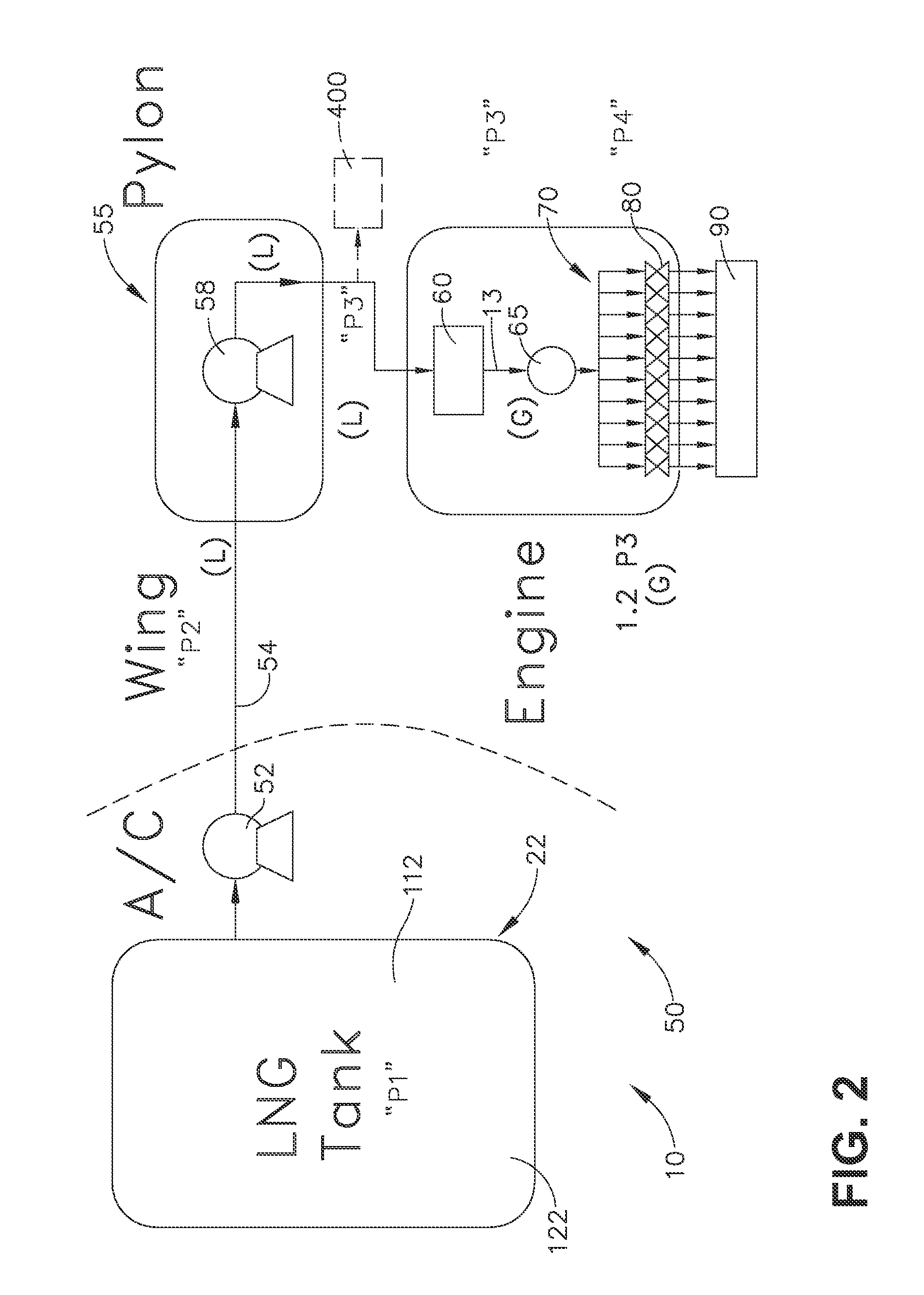
[0005]In one aspect, an embodiment of the invention relates to a turbine engine assembly including a turbine core comprising a compressor section, a combustion section, a turbine section, and a nozzle section, which are axially aligned, wherein the combustion section comprises a generally annular case having inner and outer walls, a heat exchanger comprising multiple passages in proximity to at least one of the inner and outer walls, with the passages arranged about at least a portion of the case and in fluid communication with each other such that fluid may flow through the passages, and a cryogenic fuel system having a cryogenic fuel tank with a supply line coupled to one of the passages, wherein cryogenic fuel may be supplied from the cryogenic fuel tank, through the supply line, to the passages of the heat exchanger, where the fuel in the passages may be heated by the combustion section.

[0006]In another aspect, an embodiment of the invention relates to a turbine engine assembly ...


PUM


Abstract

Turbine engine assemblies including a turbine engine assembly having a turbine core comprising a compressor section, a combustion section, a turbine section, and a nozzle section, which are axially aligned, wherein the combustion section comprises a generally annular case having inner and outer walls, a heat exchanger comprising multiple passages in proximity to at least one of the inner and outer walls, with the passages arranged about at least a portion of the case and in fluid communication with each other such that fluid may flow through the passages and a cryogenic fuel system having a cryogenic fuel tank with a supply line coupled to one of the passages, wherein cryogenic fuel may be supplied from the cryogenic fuel tank, through the supply line, to the passages of the heat exchanger, where the fuel in the passages may be heated by the combustion section. The heat exchanger may be a single or multistage vaporizer.

Description

CROSS-REFERENCE TO RELATED APPLICATIONS[0001]This application claims the benefit of U.S. Provisional Patent Application Nos. 61 / 746,847, 61 / 746,855, 61 / 746,872, 61 / 746,882, 61 / 746,915, and 61 / 746,673, all filed on Dec. 28, 2012, and all of which are incorporated herein in their entirety.BACKGROUND OF THE INVENTION[0002]The technology described herein relates generally to aircraft systems, and more specifically to aircraft systems using dual fuels in an aviation gas turbine engine and a method of operating same.[0003]Certain cryogenic fuels such as liquefied natural gas (LNG) may be cheaper than conventional jet fuels. Current approaches to cooling in conventional gas turbine applications use compressed air or conventional liquid fuel. Use of compressor air for cooling may lower efficiency of the engine system.[0004]Accordingly, it would be desirable to have aircraft systems using dual fuels in an aviation gas turbine engine. It would be desirable to have aircraft systems that can be...

Claims


Application Information

Patent Timeline
Patent Type & Authority Applications(United States)
IPC IPC(8): F02C3/22F02C7/224
CPCF02C7/224F02C3/22F02C7/16F05D2260/213F05D2260/232Y02T50/60
Inventor KUPISZEWSKI, THOMASEPSTEIN, MICHAEL JAYBUCHHOLZ, TODD JAMESDELGADO, ADONMATHIAS, CHRISTOPHER DALEOAKES, DEBORAH ANN
Owner GENERAL ELECTRIC CO
Why Eureka
Try Eureka