Fluid pressure control device

a fluid pressure control and control device technology, applied in the direction of valve operating means/releasing devices, mechanical equipment, transportation and packaging, etc., can solve the problems of increasing manufacturing costs, cost reduction, and fluid pressure control device structure, and achieve the effect of simple structur

Active Publication Date: 2015-11-26
HITACHI ASTEMO LTD
View PDF7 Cites 7 Cited by
  • Summary
  • Abstract
  • Description
  • Claims
  • Application Information

AI Technical Summary

Benefits of technology

[0006]The present invention has been made with the foregoing situation taken into consideration. An object of the present invention is to provide a low-cost fluid pressur

Problems solved by technology

The conventional fluid pressure control device, however, involves a problem of an increase in manufacturing cost, because a fixed core and a solenoid housing (yoke) are formed integrally by forging and the like.
In addition, because a part of a valve section and a part of a solenoid section, of the solenoid three-way valve,

Method used


Image

  • Fluid pressure control device
  • Fluid pressure control device
  • Fluid pressure control device

Examples


Embodiment Construction

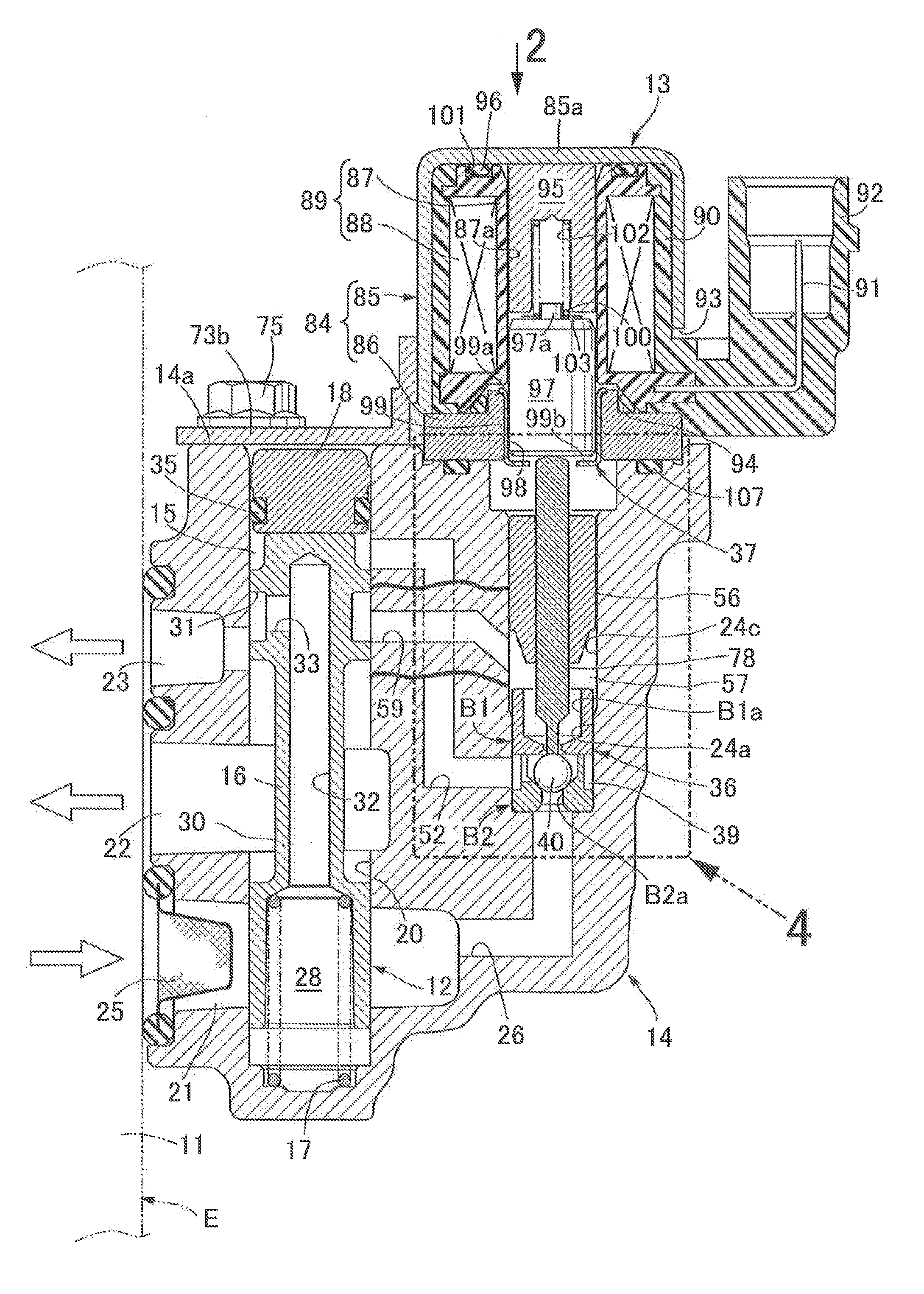
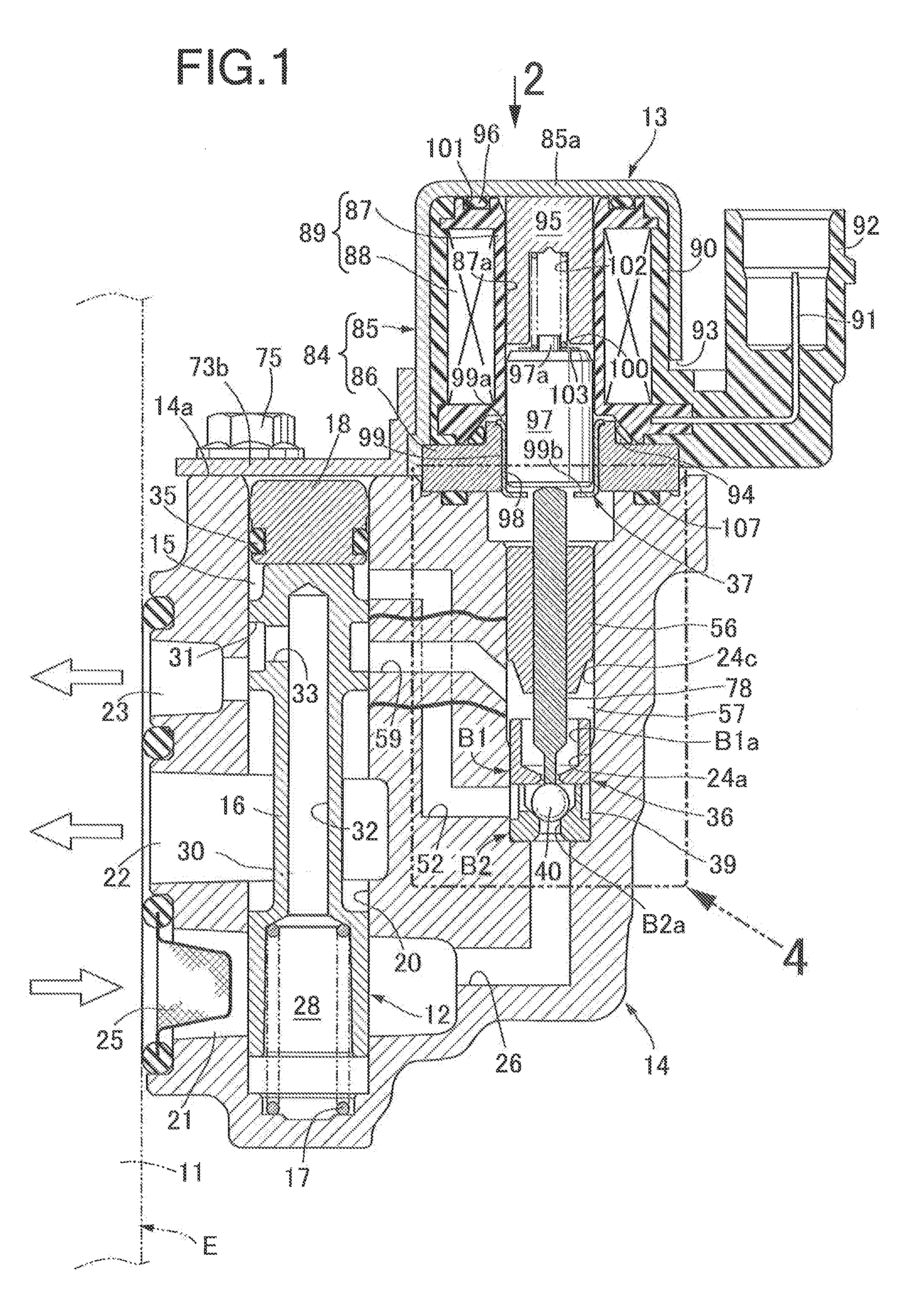
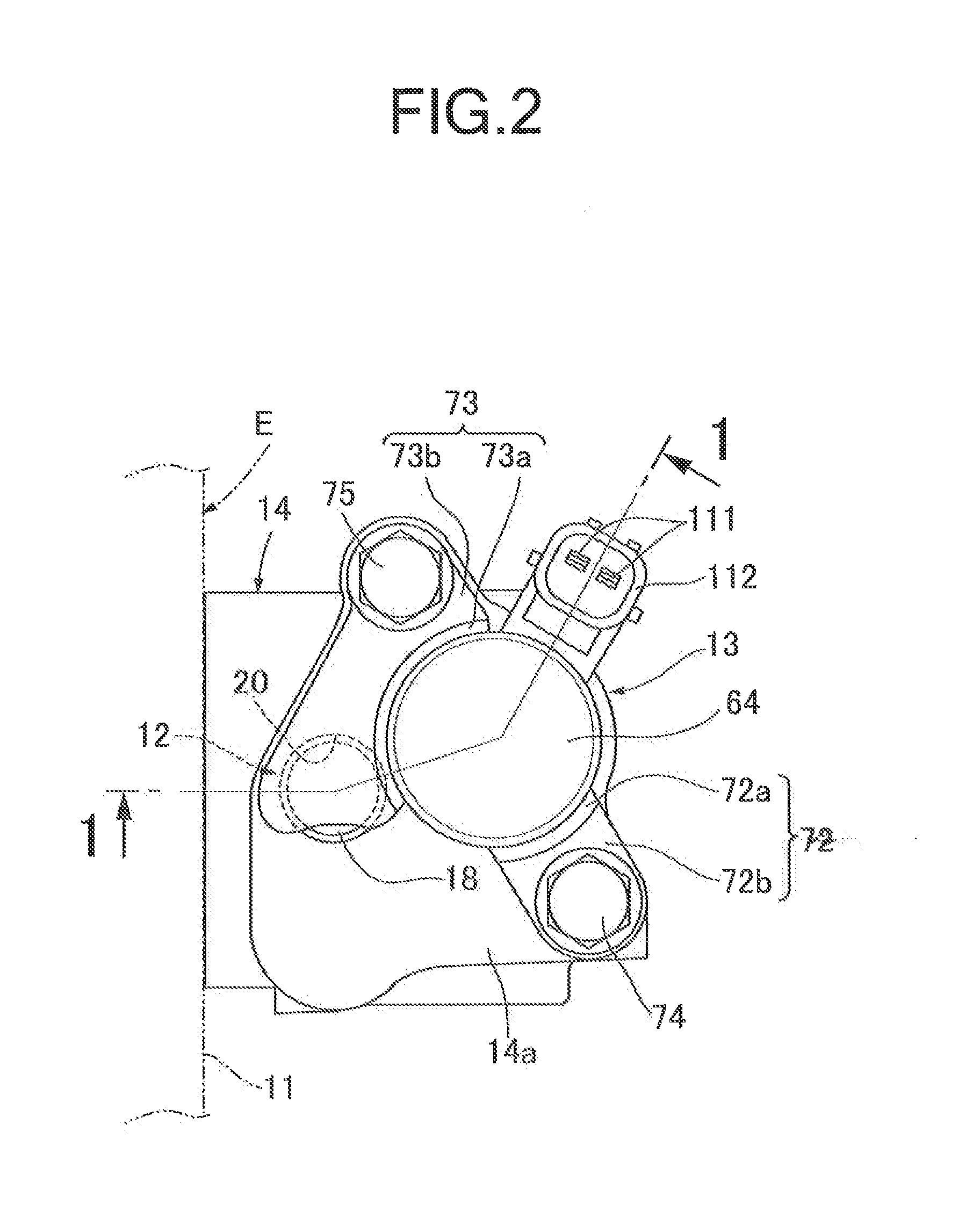
[0018]An embodiment of the present invention will be hereinbelow described on the basis of one embodiment of the present invention illustrated in the accompanying drawings.

[0019]First of all, in FIGS. 1 and 2, this fluid pressure control device is, for example, that which applies fluid pressure to a valve system in an engine E installed in a vehicle while switching the fluid pressure between high and low pressures for the purpose of changing operating characteristics of the valve system. The fluid pressure control device includes: a spool valve 12 including a valve housing 14 fastened to an engine body 11 of the engine E; and a solenoid three-way valve 13 attached to the valve housing 14 so as to be interposed between a pilot chamber 15 included in the spool valve 12 and a fluid pressure source, such as a fluid pressure pump included in the engine body 11, and the like. The solenoid three-way valve 13 is detachably attached to the valve housing 14 by fastening a pair of attachment s...


PUM


Abstract

A solenoid section of a solenoid three-way valve includes a yoke attached to a valve housing and formed from a bottomed cylindrical main yoke and an auxiliary yoke closing an open end of the main yoke, a coil assembly inside the yoke, a fixed core slidably fitted into a hollow portion of a bobbin and abutted against a ceiling wall of the main yoke, a movable core facing the fixed core and passing through the auxiliary yoke, and a coil spring compressed between the cores. The fixed core is abutted against the wall by a predetermined spring load and by electromagnetic attraction force between the core and wall based on coil energization. A valve rod is slidably supported in a housing hole, having one end separably abutted against an outer end of the movable core and an opposite end abutted against a valve body.

Description

BACKGROUND OF THE INVENTION[0001]1. Field of the Invention[0002]The present invention relates to an improvement of a fluid pressure control device which includes: a spool valve for alternatively switching communication and disconnection of an output port with and from an input port or a release port depending on whether fluid pressure is applied to or released from a pilot chamber; and a solenoid three-way valve for alternatively switching between a condition for applying the fluid pressure to the pilot chamber from the input port, and a condition for releasing the fluid pressure from the pilot chamber.[0003]2. Description of the Related Art[0004]Japanese Patent Application Laid-open No. 2003-156173 and the like have already made known the following fluid pressure control device. The spool valve and the solenoid three-way valve are disposed in a valve housing such that axes of the spool valve and the solenoid three-way valve are in parallel with each other. A size of the valve housi...

Claims


Application Information

Patent Timeline
IPC IPC(8): F16K31/06F16K11/06
CPCF16K31/061Y10T137/86879F16K11/06F16K11/0716F16K31/0631F16K31/0675F16K31/423F16K31/426Y10T137/86582Y10T137/86614F16K11/07F15B13/043
Inventor OIKAWA, NAOKIYAMANAKA, KENTAROU
Owner HITACHI ASTEMO LTD
Why Eureka
Try Eureka