Lighting unit for vehicle

a technology for vehicles and light fittings, applied in fixed installations, lighting and heating equipment, instruments, etc., can solve the problems of reducing the reliability of printing ink, reducing and reducing the aesthetic impression of buyers, so as to reduce the mechanical limit, reduce the cost, and reduce the degree of freedom in design

Active Publication Date: 2015-11-26
LG INNOTEK CO LTD
View PDF9 Cites 32 Cited by
  • Summary
  • Abstract
  • Description
  • Claims
  • Application Information

AI Technical Summary

Benefits of technology

[0015]According to some embodiments of the present invention, a composite light unit capable of implementing various light colors by changing light colors implemented in a light emitting region or by interference between light sources can be provided.
[0016]In particular, according to a first embodiment of the present invention, LEDs emitting beams having different colors are mounted to a light source module passing through a central portion of a light guide module so that two integrated beams can be implemented in one light source lamp.
[0017]Also, according to the first embodiment of the present invention, a bezel necessarily required for lighting is removed so that a surface light source for a vehicle without a bezel can be implemented, and thus a mechanical limit can be reduced, and the degree of freedom in design, diversification, and marketability can also be increased. Furthermore, two beams are implemented by one integrated light so that a taillight, a stoplight, and a turn signal lamp can be integrated, thereby enabling a reduction in costs. In particular, in order to satisfy a light distribution property, optical patterns are arranged on a surface of the light guide module so that light efficiency can be increased, and a shape of mounting grooves into which light sources are inserted is adjusted so that the problem of a defect in ejection generated upon injection of the light guide module can be solved. Moreover, when LEDs are used as light sources, a light shielding pattern for preventing hot spots of the light guide module from being generated from the LEDs is provided so that reliability can be increased.
[0018]Also, according to a second embodiment of the present invention, an individual beam is supplied to a specific region of a light emitting surface of a lighting unit for a vehicle using a patterned optical fiber so that a tail lamp, or a unique symbol, logo, and image of the vehicle can be implemented, thereby implementing differentiation in design of a rear lamp for a vehicle, and enabling an increase in marketability.
[0019]Furthermore, according to a third embodiment of the present invention, a light source module including a light guide member having a double lamination structure is formed so that various light colors can be generated by interference among beams emitted from two light sources, the degree of freedom in design can be increased.

Problems solved by technology

However, since the conventional light guide for a vehicle is mounted to a rear lamp of a vehicle body in a general form, it is problematic in that there is a limit in selecting a vehicle based on a design in terms of buyers in a state of aesthetic impression being reduced.
However, such a structure is problematic in that since the printed patterns 3-1 are used, light extraction efficiency is reduced, and reliability of a printing ink is also reduced.
Also, the structure has a limit in satisfying luminous intensity and light distribution because the light source is inserted into merely one side.

Method used


Image

  • Lighting unit for vehicle
  • Lighting unit for vehicle
  • Lighting unit for vehicle

Examples


first embodiment

1. First Embodiment

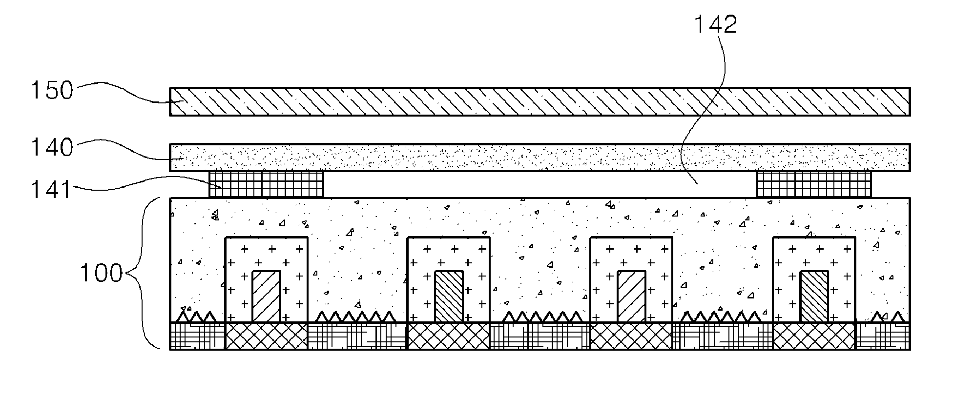
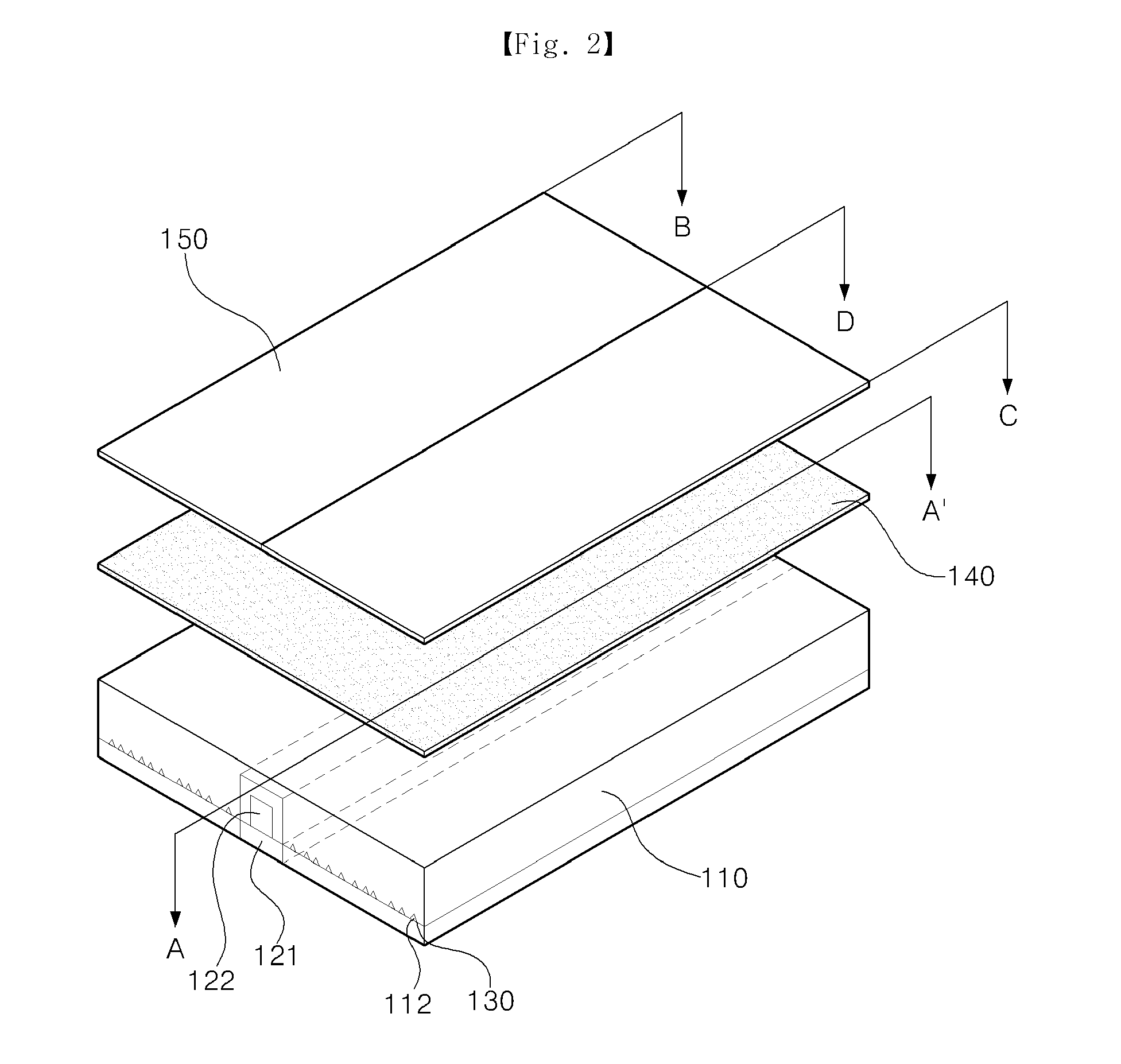
[0035]FIG. 2 conceptually illustrate a perspective view of a lighting unit according to a first embodiment of the present invention, and FIG. 3 is a conceptual view illustrating a cross section taken along lines A-A′ of FIG. 2.

[0036]Referring to FIGS. 2 and 3, a lighting unit 300 according to the present embodiment of the invention includes: a light guide module 110 including a plurality of mounting grooves111; and a light source module 120 including a plurality of LED light sources 122 inserted into the mounting grooves 111, respectively wherein each of the LED light sources 122 has at least two LEDs having different light emitting directions. That is, the lighting unit 300 according to the present embodiment of the invention is characterized in that the light sources are insertedly connected to an inner portion of the light guide module 110, and the light sources mounted on the light source module 120 are disposed to have different light emitting directions.

[003...

second embodiment

2. Second Embodiment

[0062]A lighting unit for a vehicle capable of implementing separate local light emission in a light emitting area of a light guide module according to the second embodiment of the present invention will be hereinafter described.

[0063]FIG. 11 is a conceptual view illustrating the configuration of a lighting unit for a vehicle according to the second embodiment of the present invention. Also, FIG. 12 is a conceptual view of a subject matter illustrating a cross section taken along lines A-A′ of FIG. 11.

[0064]Referring to FIGS. 11 and 12, the lighting unit for a vehicle according to the second embodiment of the invention includes: a light source module 120; a light guide module 110 adopted to guide light emitting from the light source module forward; and an optical fiber module 200 inserted into the light guide module 110 and including an optical fiber with a light reflection region implemented at an external surface. In this case, the optical fiber module 200 may ...

third embodiment

3. Third Embodiment

[0080]Unlike the structures of the first and second embodiments of the present invention, a structure of the third embodiment in which at least two light guide modules are laminated so that various light colors can be realized by interference among beams emitted from the light guide modules will be hereinafter described.

[0081]A lighting unit according to the third embodiment of the present invention can implement various light colors through a lamination structure of at least two light source modules supplying light to a light guide member.

[0082]FIG. 17 is a conceptual view illustrating the subject matters of a lighting unit for a vehicle according to the third embodiment of the present invention.

[0083]Referring to FIG. 17, the lighting unit for a vehicle according to the present invention includes: a first light source module 300 including a first light guide member 330 adopted to guide light emitted from a first light source 320; and a second light source module...


PUM


Abstract

Provided is a lighting unit for a vehicle capable of implementing surface light emission from a single light emitting surface. The light unit can function to implement a light emitting region in which at least two light colors are displayed or different light colors are implemented, or to locally emitting light.

Description

TECHNICAL FIELD[0001]Embodiments of the present invention relate to a lighting unit, and a surface light source applied to lighting for a vehicle.BACKGROUND ART[0002]A lighting unit in which various light sources used in electronic equipment are utilized has been implemented in such a manner as to increase light efficiency by utilizing an appropriate light source for each property of the electronic equipment.[0003]Even though a lighting unit, which has been recently used in electronic equipment, is a backlight unit applied to a flat display, the lighting unit may be variously applied to an indoor lamp, or a headlamp, a fog lamp, a backward light, a sidelight, a license plate light, a taillight, a turn signal lamp, a hazard flasher lamp installed at the outside of a vehicle, or an indoor lighting lamp installed at the inside of a vehicle.[0004]However, the most of lighting is mainly realized by a method of increasing luminance of a surface light source by applying a member such as a ...

Claims


Application Information

Patent Timeline
Patent Type & Authority Applications(United States)
IPC IPC(8): F21S8/10F21V8/00
CPCF21S48/2243F21S48/2268G02B6/0021G02B6/0068F21Y2101/02G02B6/0051G02B6/0036G02B6/0083G02B6/0073F21S43/239F21S43/245G02B6/001G02B6/0076
Inventor AHN, KYOUNG SOOLEE, JEONG OH
Owner LG INNOTEK CO LTD
Why Eureka
Try Eureka