Device for monitoring biofilm

a biofilm and monitoring device technology, applied in the field of biofilm monitoring devices, can solve the problems of large amount of cost and complicated system, method is not suitable for real-time monitoring in which the formation of biofilm can be continuously monitored, and method is not suitable for real-time monitoring, so as to reduce measurement errors, reduce cost, and simple and low-priced device

Active Publication Date: 2015-11-26
KOREA UNIV RES & BUSINESS FOUND
View PDF9 Cites 5 Cited by
  • Summary
  • Abstract
  • Description
  • Claims
  • Application Information

AI Technical Summary

Benefits of technology

[0012]In the device according to the present invention, it is possible to continuously observe the formation state of a biofilm without any separate reagent while using a simple and low-priced device.
[0013]Further, it is possible to automate, with the development of computer software combined with a simple image processing technique, information that was acquired only using various types of measuring equipments such as an enzyme-linked immunosorbent assay (ELISA) reader and a photospectrometer through processes in which skilled inspectors or engineers collect samples and perform separate dyeing or attachment of an identifier. Thus, it is possible to decrease cost and remarkably reduce measurement errors.
[0014]Further, pixel values of shadow images of biofilms formed by bacteria are used, so that it is possible to easily analyze formation degrees of biofilms without any high-priced device.

Problems solved by technology

In the above-described methods, high-priced exclusive equipments such as an ELISA reader and a photospectrometer are used, and therefore, a large amount of cost and a complicated system are required.
Therefore, the methods are not suitable for real-time monitoring in which the formation of a biofilm can be continuously monitored.
However, in Korean Patent Publication No. 10-2005-0007540, a separate reagent is necessarily required to measure a formation state of the biofilm, and therefore, the method is not suitable for real-time monitoring in which the formation of the biofilm can be continuously monitored.

Method used


Image

  • Device for monitoring biofilm
  • Device for monitoring biofilm
  • Device for monitoring biofilm

Examples


Embodiment Construction

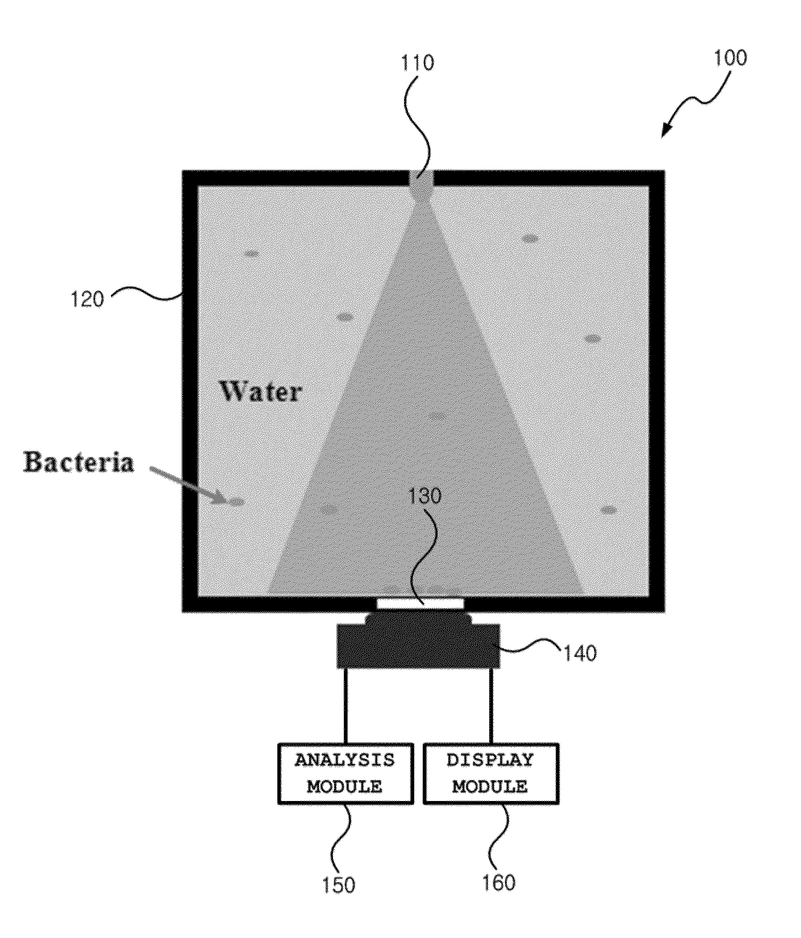
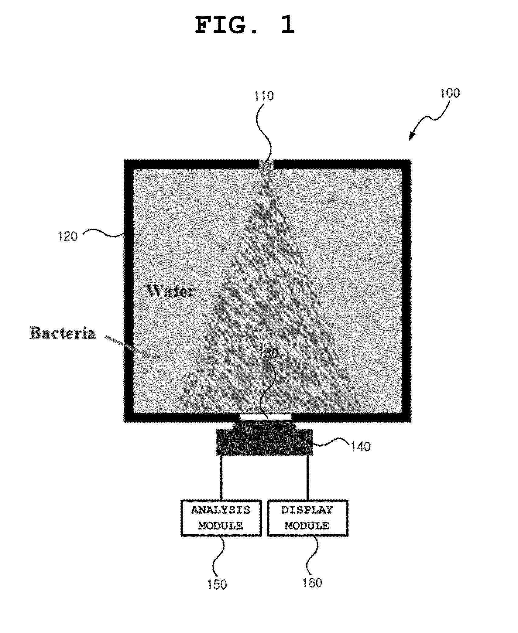
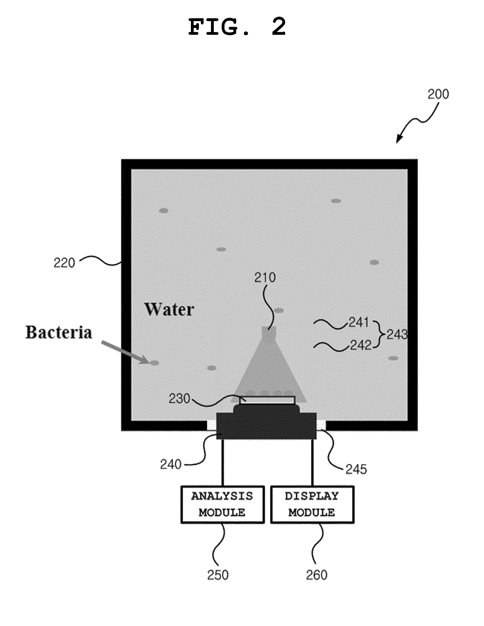
[0022]Hereinafter, a device for monitoring a biofilm and a method of analyzing a formation state of a biofilm by using the device according to an embodiment of the present invention will be described with reference to the accompanying drawings.

[0023]As used herein, the singular terms are intended to include the plural forms as well, unless the context clearly indicates otherwise. It will be further understood that the terms “includes” and / or “including”, when used in this specification, specify the presence of stated features, integers, steps, operations, elements, and / or components, but do not preclude the presence and / or addition of one or more other features, integers, steps, operations, elements, components, and / or groups thereof.

[0024]A device for monitoring a biofilm according to an embodiment of the present invention can accelerate the formation of a biofilm existing in water and monitor a formation state of the biofilm by using a shadow image of the biofilm.

[0025]A biofilm i...


PUM

PropertyMeasurementUnit
transparentaaaaaaaaaa
adsorptionaaaaaaaaaa
absorbanceaaaaaaaaaa

Abstract

The present invention relates to a device for monitoring a biofilm, which can monitor a formation state of the biofilm by using a biofilm shadow image. According to one embodiment of the present invention, the device for monitoring a biofilm can comprise: a water tank for storing water; a monitoring substrate arranged inside the water tank and surface-treated so as to accelerate the biofilm formation; a light-emitting module located at an upper portion of the monitoring substrate so as to emit light in a monitoring substrate direction; and an image sensor unit arranged below the monitoring substrate so as to capture a shadow image of the biofilm, which is formed on the monitoring substrate.

Description

TECHNICAL FIELD[0001]The present invention relates to a device for monitoring a biofilm, and more particularly, to a device for monitoring a biofilm, which can monitor a formation state of the biofilm by using a shadow image of the biofilm.BACKGROUND ART[0002]Biofilms are biological films which are produced as specific bacteria are proliferated on specific surfaces through processes of adsorption, growth, and desorption. Traditionally, techniques for measuring the biofilms are as follows.[0003]Enzyme-linked immunosorbent assay (ELISA) is a technique of measuring absorbance, light emission, or fluorescence by selectively reacting only cells in a specific state, using an antibody having high singularity and high sensitivity and an enzyme serving as a signal generating source.[0004]Photospectrometry is a technique in which bacteria that become the source of a biofilm are dyed with a specific kind of reagent, and the dyed sample is dissolved with a solvent such as alcohol, so that the c...

Claims


Application Information

Patent Timeline
Patent Type & Authority Applications(United States)
IPC IPC(8): G01N21/84G01N33/487
CPCG01N21/8422G01N2201/061G01N33/4875G01N21/00G01N33/48785G01N33/483
Inventor SEO, SUNG-KYUHA, UN-HWAN
Owner KOREA UNIV RES & BUSINESS FOUND
Why Eureka
Try Eureka