
Method of fuel injection for a variable displacement engine

a variable displacement, fuel injection technology, applied in the direction of machines/engines, electric control, ignition automatic control, etc., can solve the problems of partial burn, vde engine configuration with only port fuel injection system may have problems during transition between vde, emissions and drivability issues may increase, etc., to achieve a wide range of engine configurations, reduce displacement, and increase fuel economy

Active Publication Date: 2015-12-03
FORD GLOBAL TECH LLC
View PDF41 Cites 40 Cited by
  • Summary
  • Abstract
  • Description
  • Claims
  • Application Information

AI Technical Summary

Benefits of technology

The patent describes a method for controlling fuel injection in an engine with deactivatable cylinders to improve fuel economy and reduce emissions. By decreasing the amount of fuel injected by one injector and increasing the amount injected by another, the engine can operate at a higher manifold pressure and reduce friction. This allows for a fresh air charge to be trapped within the deactivated cylinders, resulting in improved engine performance and reduced emissions. Additionally, by controlling the fuel injection ratios during engine operation transitions, engine performance and emissions can be improved.

Problems solved by technology

As such, VDE engines configured with only port fuel injection systems may have problems during transitions between VDE and non-VDE modes of operation.
Further, without an established intake port fuel puddle during the transition, fuelling errors may occur, and emissions and drivability issues may increase due to degraded combustion stability.
Specifically, the trapped air charge may include a portion of fuel drawn in from the puddle which may lead to partial burn and / or misfire when the charge is sparked upon reactivation.
Alternatively, if the trapped air charge with fuel is expelled without being combusted, unburned hydrocarbons in the exhaust may elevate catalyst temperature leading to degradation of the catalyst.

Method used


Image

  • Method of fuel injection for a variable displacement engine
  • Method of fuel injection for a variable displacement engine
  • Method of fuel injection for a variable displacement engine

Examples


Embodiment Construction

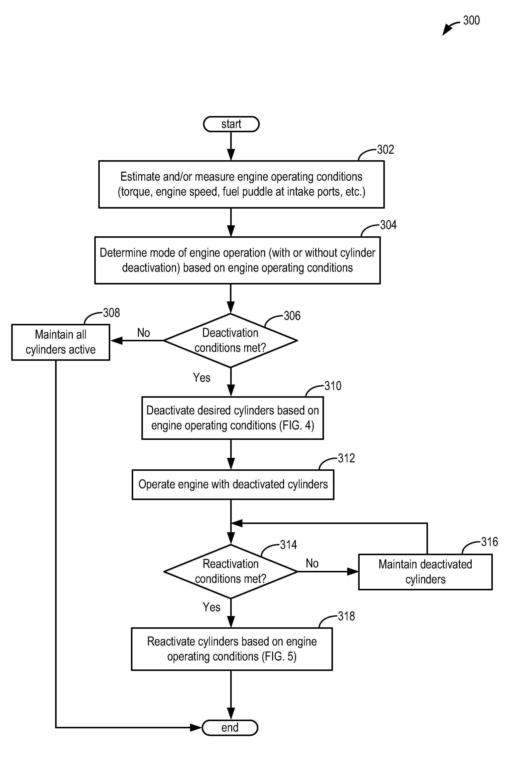
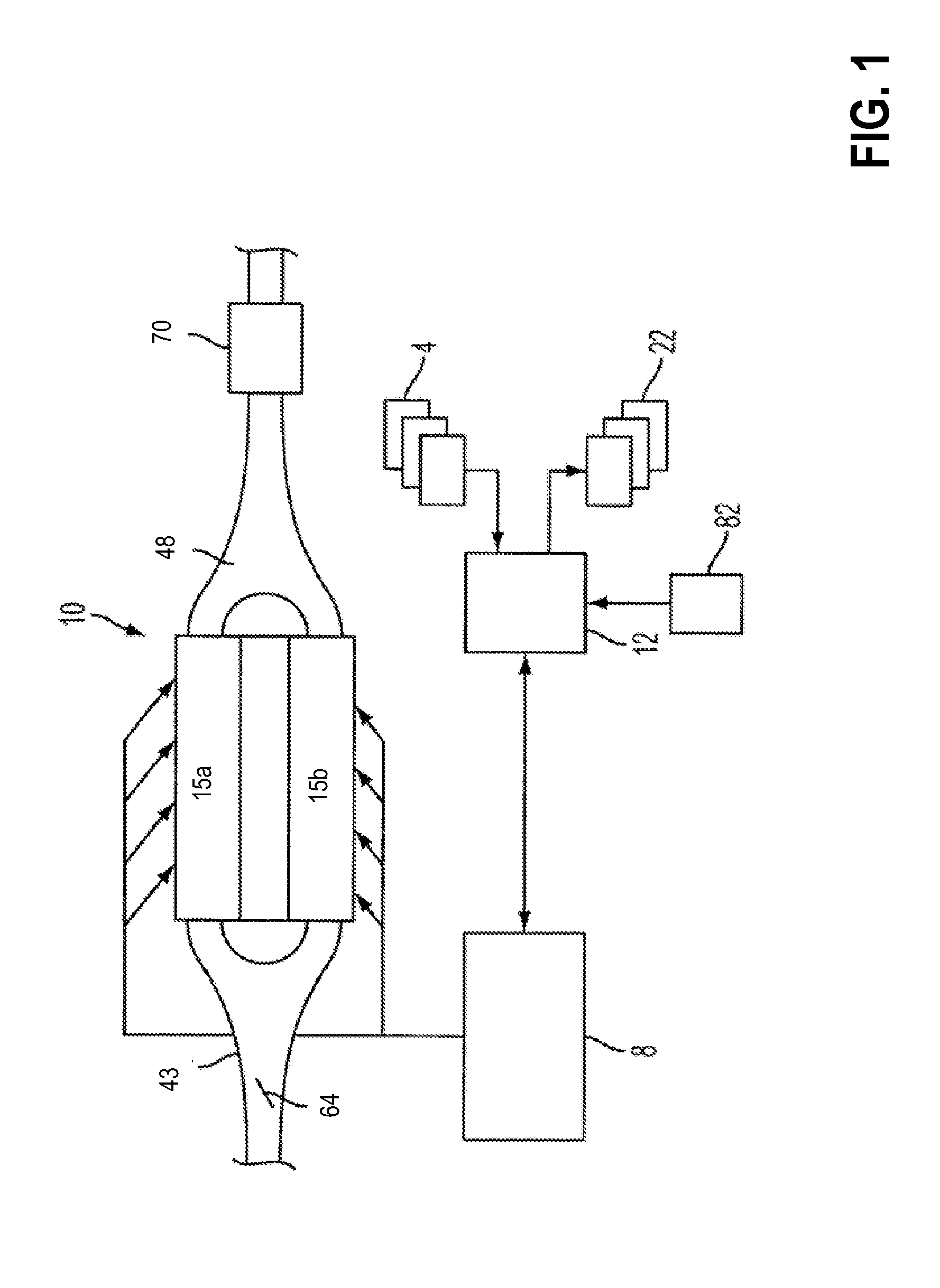
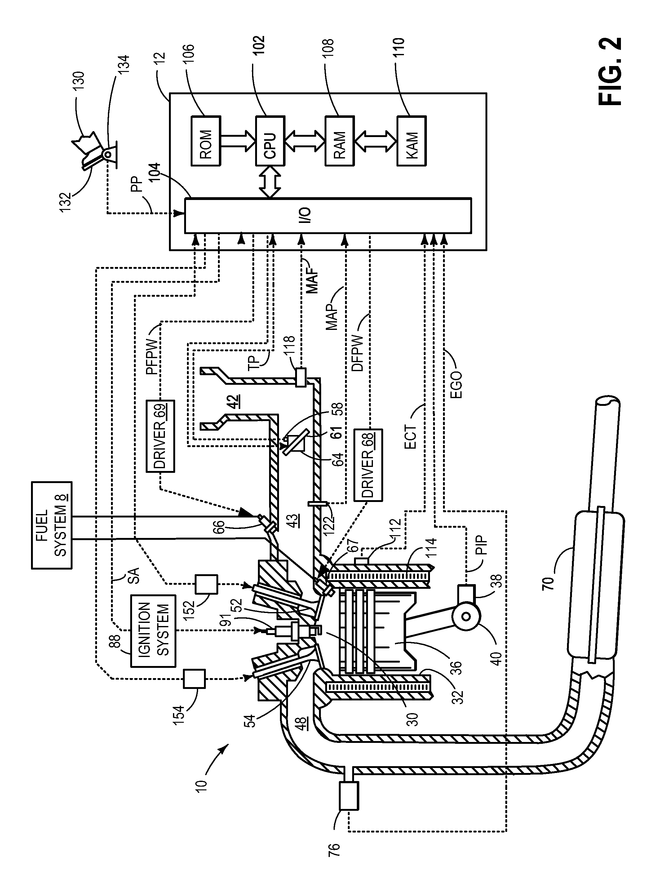
[0017]Methods and systems are described for adjusting fuel injection profiles in selectively deactivatable cylinders of a variable displacement engine (VDE), such as the engine system shown in FIG. 1. Each cylinder in the VDE may be configured with a port injector and a direct injector as shown in FIG. 2. A controller may be configured to transition engine operation from VDE mode to non-VDE mode, or vice versa, based on operating conditions (FIG. 3). A fuel injection profile in a cylinder selected for deactivation may be adjusted such that an intake port fuel puddle is consumed before the cylinder is deactivated and a fresh air charge is trapped (FIG. 4). Additionally, the fuel injection profile may be adjusted in a reactivated cylinder to allow an accumulation of the intake port fuel puddle before port injection is ramped up (FIGS. 5-6). Various operating parameters may be adjusted (FIG. 7), as fuel injection profiles are modified based on cylinder deactivation and reactivation, to...


PUM


Abstract

Various systems and methods are described for controlling fuel injection in a variable displacement engine. One method for a deactivatable cylinder comprises, before deactivating the cylinder responsive to operating conditions, disabling a port injector and fueling the cylinder only via the direct injector. The method further comprises, when reactivating the cylinder from deactivation, enabling both the port injector and the direct injector, and injecting a higher amount of fuel via the direct injector while simultaneously injecting a lower amount of fuel via the port injector.

Description

TECHNICAL FIELD[0001]The present application relates to controlling fuel injection in a variable displacement engine.BACKGROUND AND SUMMARY[0002]Engines may be configured to operate with a variable number of active or deactivated cylinders to increase fuel economy, while optionally maintaining the overall exhaust mixture air-fuel ratio about stoichiometry. Such engines are known as variable displacement engines (VDE). In some examples, a portion of an engine's cylinders may be disabled during selected conditions, where the selected conditions can be defined by parameters such as a speed / load window, as well as various other operating conditions including vehicle speed. A VDE control system may disable selected cylinders through the control of a plurality of cylinder valve deactivators that affect the operation of the cylinder's intake and exhaust valves, and / or through the control of a plurality of selectively deactivatable fuel injectors that affect cylinder fueling. By reducing di...

Claims


Application Information

Patent Timeline
IPC IPC(8): F02D17/02F02P5/04F02D41/30
CPCF02D17/02F02P5/045F02D41/3094F02D41/047F01L13/0005F01L2013/001F02D2041/389F01L2800/03F02D41/008F02D41/0087F02D41/0002F02D41/345F02D41/402F02D2200/0406F02D2200/0414F02D2200/0614F02D2200/60
Inventor GLUGLA, CHRIS PAULSURNILLA, GOPICHANDRA
Owner FORD GLOBAL TECH LLC
Learn More