Monitoring and Control Systems for the Agricultural Industry

a technology for monitoring and control systems in the agricultural industry, applied in the field of precision agriculture, can solve the problems of affecting the performance of the network, affecting the success of the sensor network over the relatively large area covered by the farm, and the number of sensor nodes in the network is large, so as to achieve effective management

Active Publication Date: 2015-12-10
SEMIOSBIO TECH
View PDF6 Cites 21 Cited by
  • Summary
  • Abstract
  • Description
  • Claims
  • Application Information

AI Technical Summary

Problems solved by technology

In practice, the successful implementation of sensor networks over the relatively large areas covered by a farm, vineyard or orchard has faced challenges and obstacles.
This results in the relatively large number of sensor nodes in the network being awake and transmitting or retransmitting at substantially the same time.
The inventors have found that this results in interference and collisions that must be managed and that degrade the performance of the network.
However, any enlargement of the awake time is at the direct (and almost inversely proportional) expense of battery life.
An additional challenge in the use of wireless sensor mesh networks in agricultural applications is that the optimal location of the sensors is often on the trunk of the plant or within its foliage in which case the vegetation itself acts as an obstruction to signal propagation.
This threatens to orphan some nodes in the mesh network or to require more retransmissions and impose a greater network management burden, again drawing more power from the battery.
More significantly, placing a sensor unit in or beneath the foliage severely restricts the available insolation for solar panels, particularly in more challenging climates.
The foregoing considerations combine to severely compromise the ability of the sensors to operate according to a mesh network protocol in agricultural applications where there are many sensor nodes or they are deployed within or under the foliage.
While the agricultural industry is moving toward fully organic farming by reducing pesticide usage, such a reduction requires precision control of insect infestations, which is economically challenging in view of the labor-intensive approach to insect detection.

Method used


Image

  • Monitoring and Control Systems for the Agricultural Industry
  • Monitoring and Control Systems for the Agricultural Industry
  • Monitoring and Control Systems for the Agricultural Industry

Examples


Embodiment Construction

[0037]The preferred embodiment of the monitoring and control system of the invention will be described by reference to an insect management system.

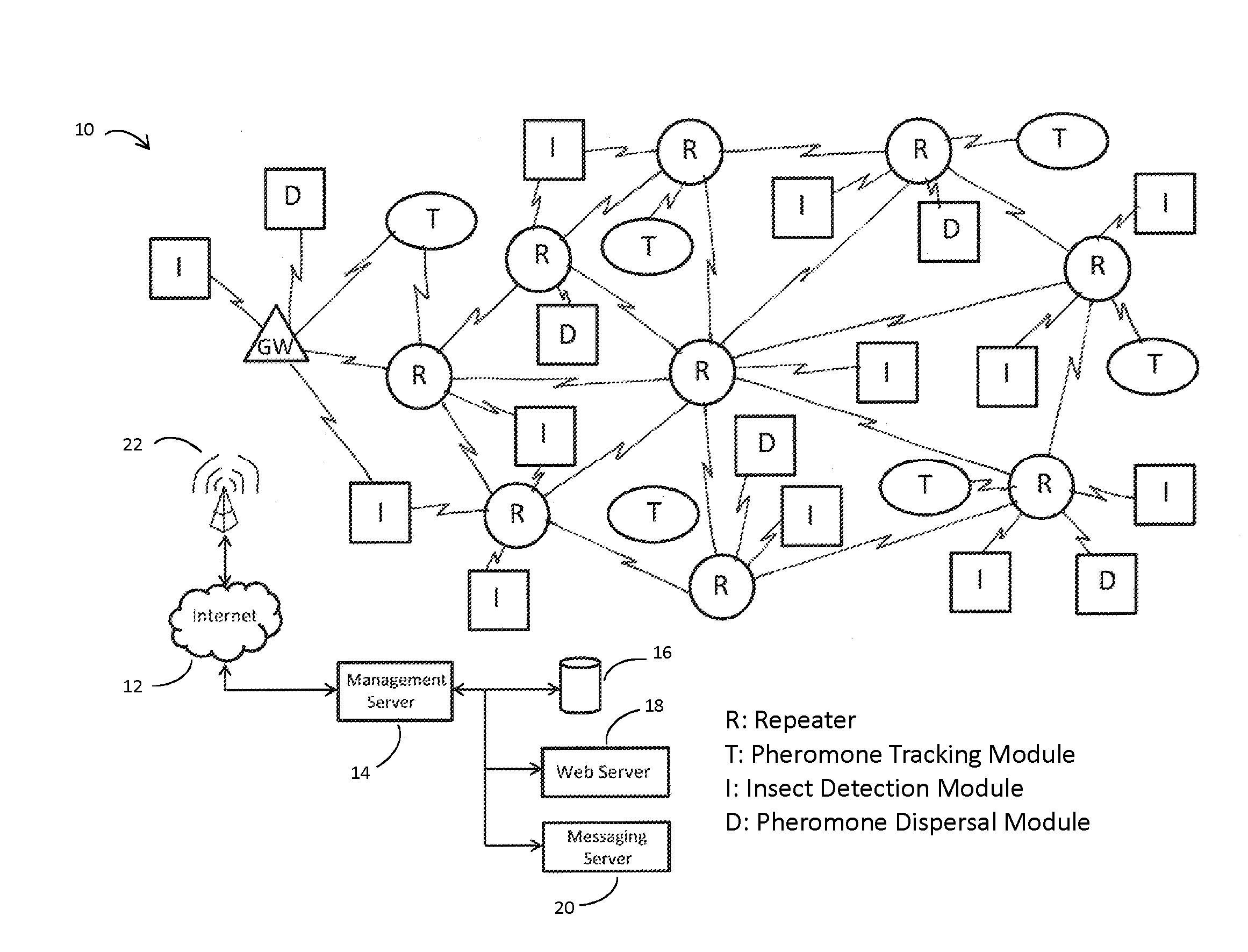
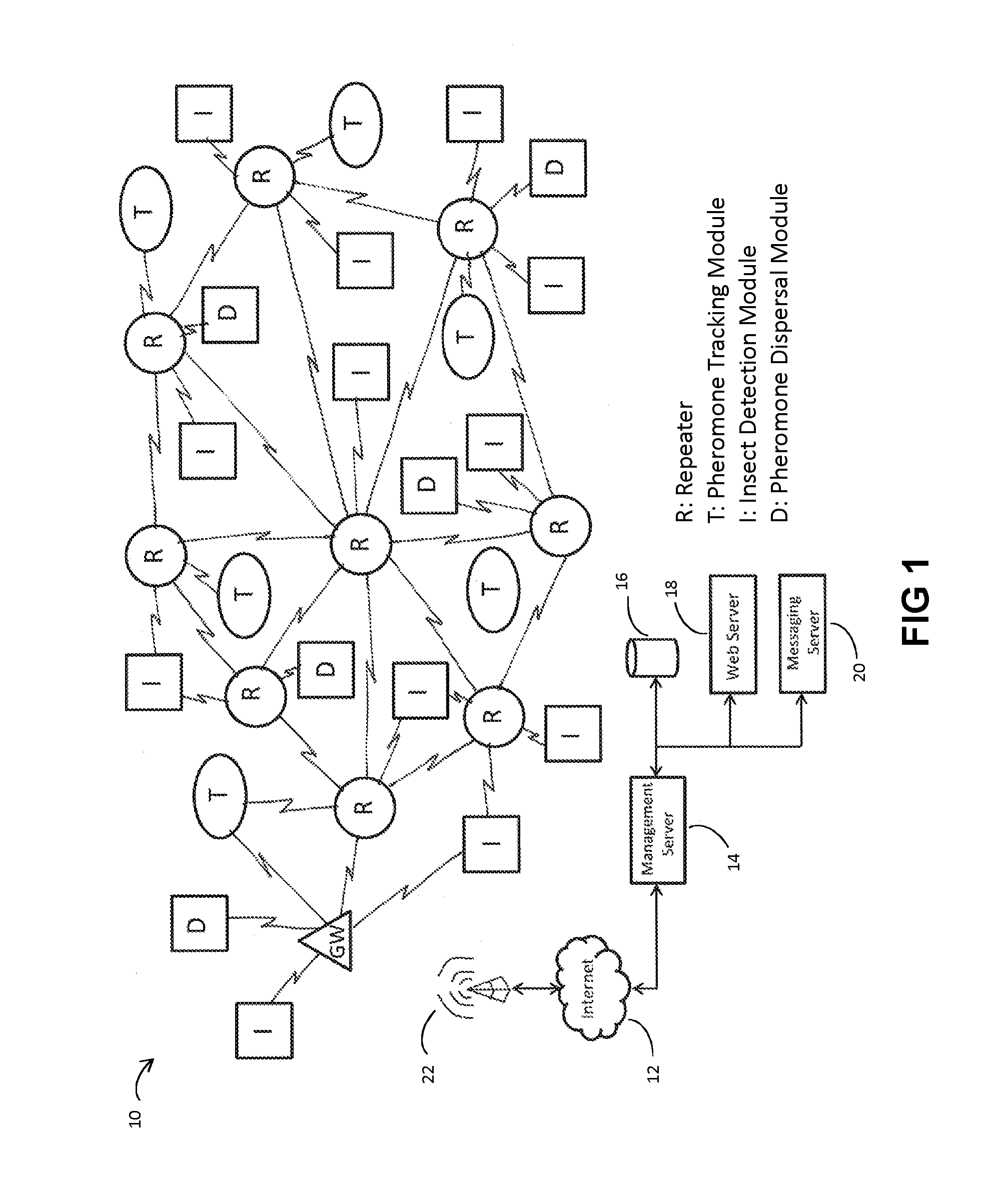
[0038]FIG. 1 provides an overview of the system network 10 as deployed in relation to an agricultural production area. In the preferred illustrative embodiment, the production area is an orchard. The Internet represents what is now commonly referred to as the “cloud”. It should also be appreciated that although the figure shows three types of sensor and actuation modules (namely pheromone tracking modules T, insect detection modules I and pheromone dispersal modules D), other types of sensor and actuator modules may actually be used in a similar network. In addition, the figure does not separately illustrate the weather modules that are mounted along with the repeaters in the preferred embodiment, as discussed in more detail below.

[0039]A plurality of insect detection modules I are arrayed throughout the orchard, including within and unde...


PUM


Abstract

A mesh-based wireless network 10 of sensor / actuator devices I, D, T for an agricultural production area involves battery-powered sensors and actuators deployed under or within the foliage for broadcast communication with at least one repeater R according to broadcast time slots. The repeaters R are mounted above the vegetation canopy so as to be powered by solar panels. The repeaters R form a mesh network for routing data and commands to and from the sensors and actuators and at least one gateway GW. The gateway communicates over a cellular network with a remote agricultural management server 14 and database 16.

Description

FIELD OF THE INVENTION[0001]This invention relates to precision agriculture and to the application of apparatus and networking approaches to support precision agriculture. In another aspect the invention relates to monitoring and control systems for agricultural production areas. In particular this invention relates to a wireless network of sensors and actuators, and a remote server and database for data analysis, dissemination of information distribution and integrated control of the actuators.BACKGROUND OF THE INVENTION[0002]Precision agriculture involves observing and responding to localized field conditions on a farm, vineyard or orchard using technologies such as aerial and satellite imagery, sensor arrays and geographic information systems, so as to optimize field-level management. The process involves matching the topology of a production area with the geo-location of data, such as climactic conditions, soil conditions, weeds and diseases, across the area to be managed.[0003]...

Claims


Application Information

Patent Timeline
Patent Type & Authority Applications(United States)
IPC IPC(8): A01G25/16H04B7/155H04W72/04H04L29/08H04W72/00
CPCA01G25/16H04L67/125H04W84/18H04W72/0446H04B7/15542H04W72/005A01B79/005A01M1/026A01M1/14A01M1/145H04W72/30
Inventor GILBERT, MICHAELMETCALFE, LEONARD
Owner SEMIOSBIO TECH
Why Eureka
Try Eureka