Position-detecting device, respiration measurement device and heart rate measurement device

a technology of respiration measurement and detecting device, which is applied in the field of position detection device, respiration measurement device and heart rate measurement device, can solve problems such as increasing information processing quantity, and achieve the effect of increasing information processing quantity

Active Publication Date: 2015-12-10
SUMITOMO RIKO CO LTD
View PDF2 Cites 11 Cited by
  • Summary
  • Abstract
  • Description
  • Claims
  • Application Information

AI Technical Summary

Benefits of technology

[0011]With the conventional apparatuses, the pressure distribution of the entire body is obtained first, then, the entire distribution is analyzed to detect the positions of the respective body parts. Therefore, when detecting the position of the respective body parts, it is required to acquire the pressure distribution in a wide range and analyze the distribution, which results in increased information processing quantity.

Problems solved by technology

Therefore, when detecting the position of the respective body parts, it is required to acquire the pressure distribution in a wide range and analyze the distribution, which results in increased information processing quantity.

Method used


Image

  • Position-detecting device, respiration measurement device and heart rate measurement device
  • Position-detecting device, respiration measurement device and heart rate measurement device
  • Position-detecting device, respiration measurement device and heart rate measurement device

Examples


first embodiment

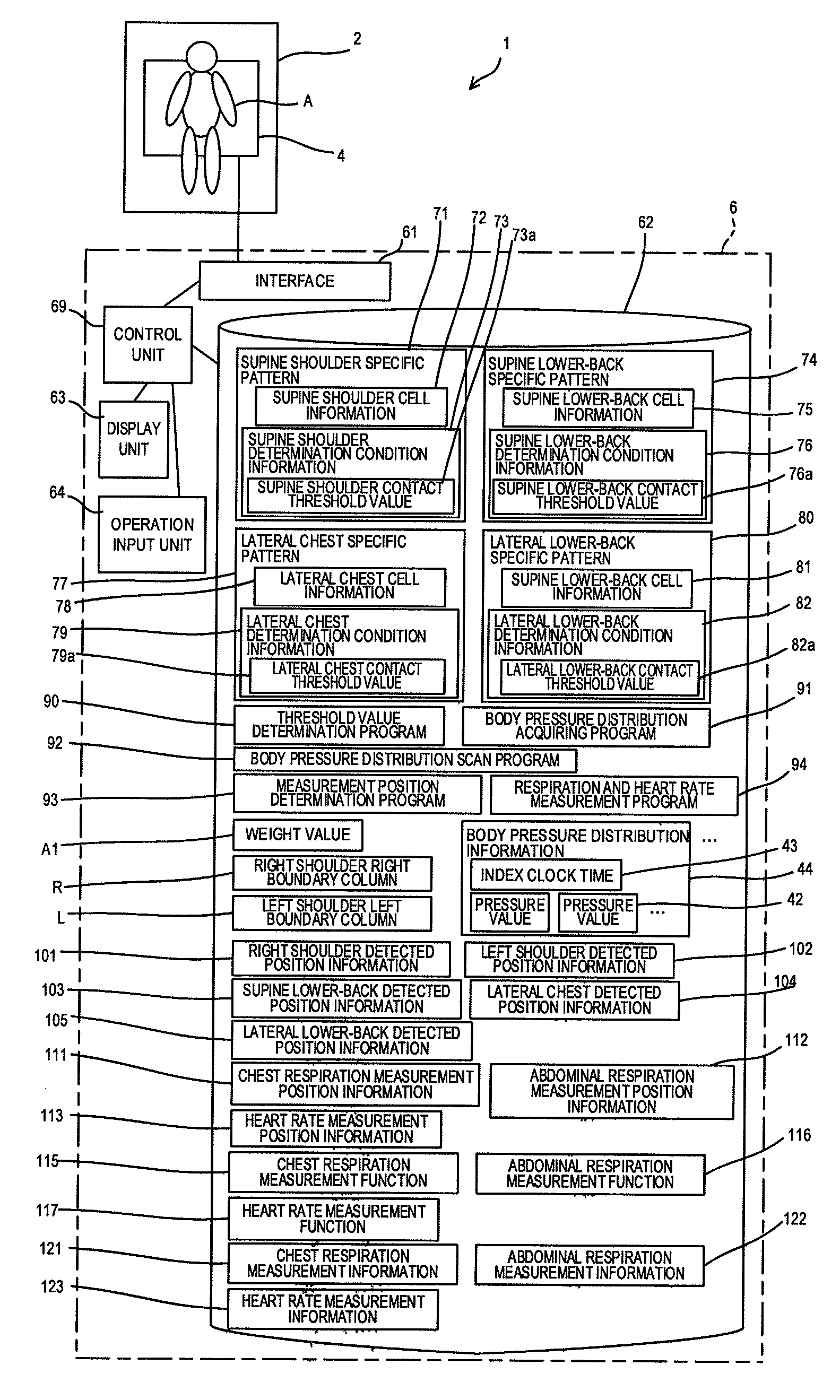
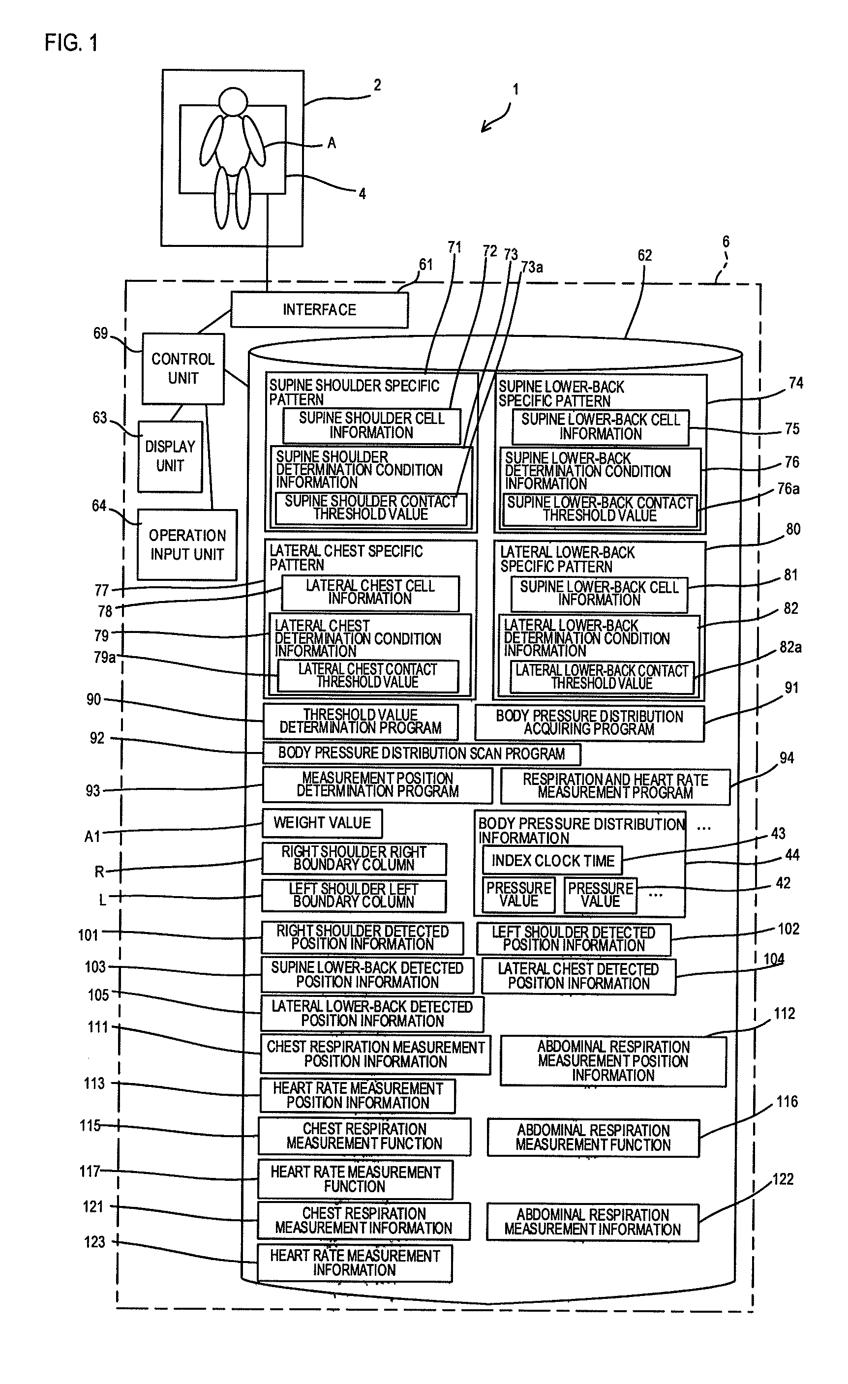
[0047]FIG. 1 is a schematic drawing of a position-detecting device 1 according to the present invention. The position-detecting device 1 includes bedclothes 2, a body pressure distribution sensor 4 placed on the bedclothes 2, and a computer 6.

[0048]The bedclothes 2 are equipment that allows a sleeper A as a user of the position-detecting device 1 to sleep thereon, and here, is a bed. However, mattress or Japanese-style bedding is also applicable.

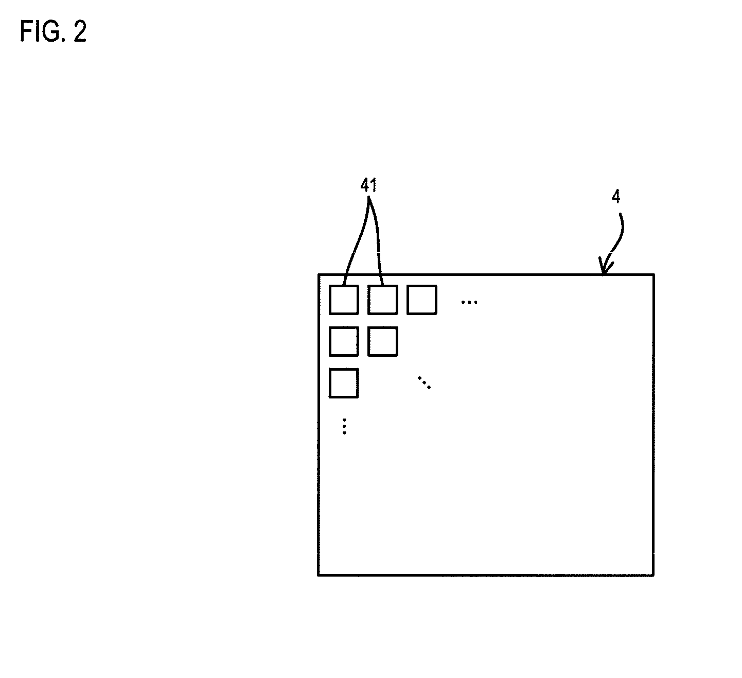
[0049]The body pressure distribution sensor 4 is a mat-like sensor having a plurality of pressure sensors 41, 41 . . . as illustrated in FIG. 2.

[0050]The pressure sensors 41, 41 . . . are arranged in a matrix pattern having rows and columns, and are arranged, for example, to have sixteen rows and sixteen columns. However, the numbers of the rows and the columns may be increased or decreased. The sizes of sensible ranges of the respective pressure sensors 41 may be set variously. In addition, even though the pressure sensors 41, 41 . . . are ...

second embodiment

[0185]In the second embodiment, as illustrated in FIG. 13A, the cells C, C . . . of two rows and two columns on the left side, the cells C, C . . . of two rows and two columns on the right side, and blank cells K, K . . . , which are blank, of two rows and two columns therebetween are used as the supine chest specified pattern 271.

[0186]The control unit 69 executes the supine chest scanning process instead of the supine shoulder scanning process S31 in the first embodiment. In this processing, the control unit 69 applies the supine chest specified pattern 271 to the body pressure distribution information 44 in sequence from the upper left corner, and performs scanning on the chest portion in the supine position. The reference cell C of the supine chest specified pattern 271 is the upper left corner. The condition of determining the chest portion here is that the sum (or an average) of the pressure values 42, 42 . . . at the eight cells C, C . . . in total is not smaller than the pre...


PUM


Abstract

A position-detecting device includes a body pressure distribution sensor including a plurality of pressure sensors that outputs pressure signals corresponding to pressure values respectively and are arranged in a matrix pattern, a specific pattern storage unit storing a range that pressure sensors can occupy and a condition of pressure values relating to the pressure sensors within the range as a specific pattern by sleeping posture and body part of a sleeper, a scanning unit applying the specific pattern to body pressure distribution information, which is a set of the pressure values, from a scan starting position to an adjacent position in sequence and to determine whether the condition is satisfied, and a body part position determining unit determining the position of the body part in the sleeping posture corresponding to the position of the specific pattern in the body pressure distribution information when the condition is satisfied.

Description

[0001]This application is a Continuation of International Application No. PCT / JP2014 / 053032, filed on Feb. 10, 2014, which claims the benefit of Japanese Patent Application Number 2013-024181 filed on Feb. 12, 2013, the disclosures of which are incorporated by reference herein in their entireties.BACKGROUND OF INVENTION[0002]1. Technical Field[0003]The present invention relates to a position-detecting device configured to detect positions of respective body parts of a sleeper using a body pressure distribution sensor including pressure sensors arranged in a matrix pattern. The present invention also relates to a respiration measurement device and a heart rate measurement device configured to detect a respiration measurement position and a heart rate measurement position of the sleeper using the position-detecting device to measure states of respiration and heart rate.[0004]2. Background Art[0005]There is known a sleeping apparatus configured to detect a body movement or a position o...

Claims


Application Information

Patent Timeline
Patent Type & Authority Applications(United States)
IPC IPC(8): A61B5/00A61B5/11A61B5/113A61B5/024A61B5/08
CPCA61B5/6892A61B5/02444A61B5/0816A61B2562/0247A61B5/11A61B5/4806A61B5/113A61B5/1116A61B5/6891A61B2562/046
Inventor SHIMIZU, ATSUKIMAEDA, ICHINOSUKE
Owner SUMITOMO RIKO CO LTD
Why Eureka
Try Eureka