
Blow-by gas recirculation apparatus

a blow-by gas and recirculation apparatus technology, which is applied in the direction of machines/engines, casings, combustion engines, etc., can solve the problems of increased costs, complicated apparatus configuration, and moisture of blow-by gas remaining inside the pcv valv

Inactive Publication Date: 2015-12-10
AISIN SEIKI KK
View PDF5 Cites 15 Cited by
  • Summary
  • Abstract
  • Description
  • Claims
  • Application Information

AI Technical Summary

Benefits of technology

The patent describes a configuration for a device used in an engine. The device uses heated oil to remove freezing from a PCV valve, which can otherwise become blocked in cold temperatures. The oil is heated at the engine and then sent to the PCV valve to remove the freeze. The oil has a higher specific heat compared to coolant water, so it can quickly reach a high temperature and transfer heat to the PCV valve. The device also has a heating space where the oil is sprayed to heat the valve without wasting oil or losing heat through the inner wall of the space. The combination of heat transfer from the metal material to the PCV valve and the high coefficient of thermal conductivity of metal also helps to quickly remove any freezing. Overall, the device provides a more efficient and effective solution for preventing blockages in the engine.

Problems solved by technology

For example, in a case where the engine stops in a cold district, the moisture of the blow-by gas remaining inside a PCV valve may freeze.
Accordingly, the configuration of the apparatus is complicated, thereby leading to, for example, increased costs and thus there is room for improvement.
To the contrary, according to the configuration using the coolant water of the engine as a heat source, the configuration is simple because the control apparatus is unnecessary.
However, it takes time for temperature of the coolant water to rise, and the freezing cannot be released quickly.

Method used


Image

  • Blow-by gas recirculation apparatus
  • Blow-by gas recirculation apparatus
  • Blow-by gas recirculation apparatus

Examples


Embodiment Construction

[0026]An embodiment of the present invention will be described hereunder with reference to the drawings.

[Basic Configuration]

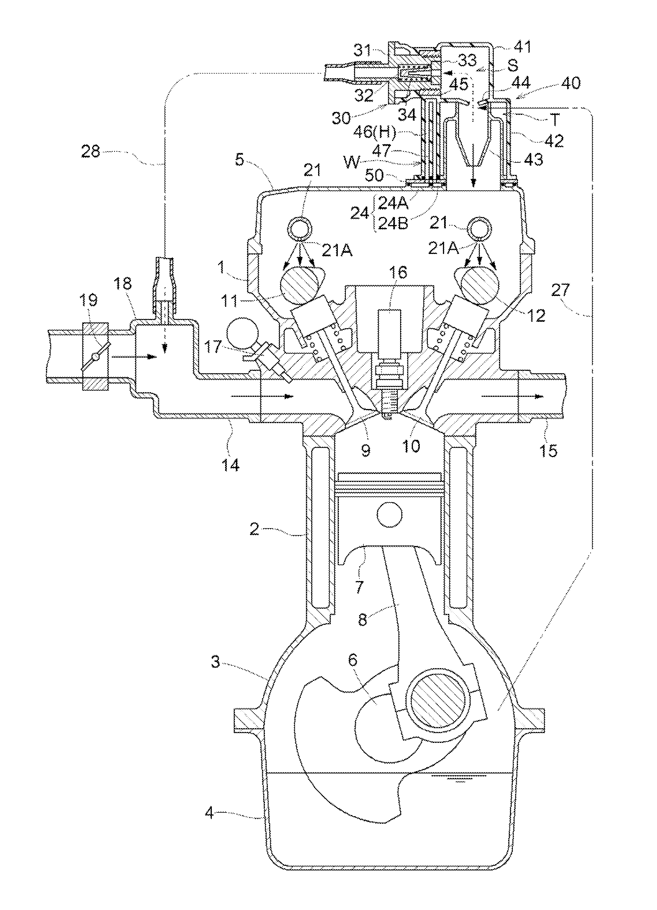
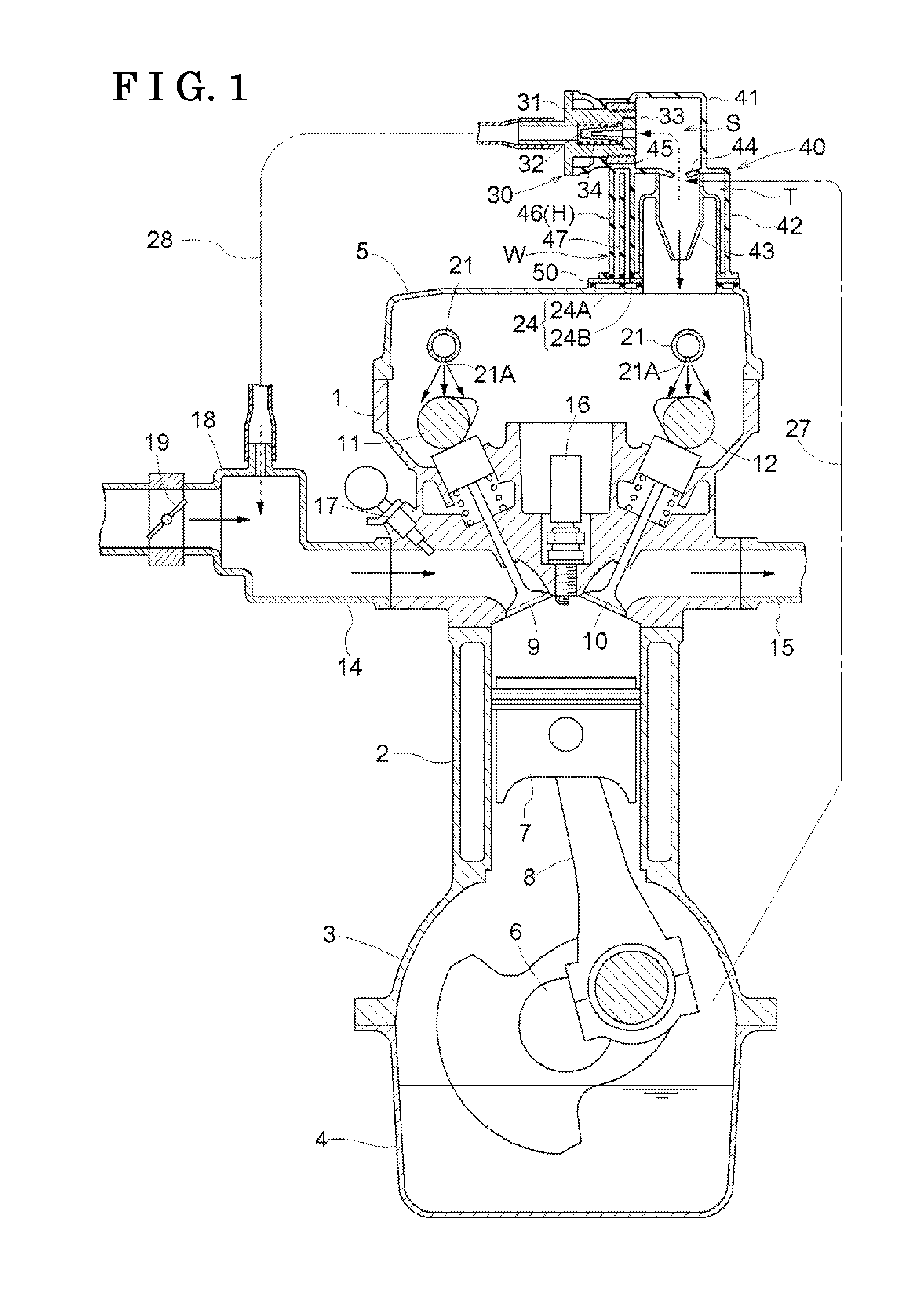
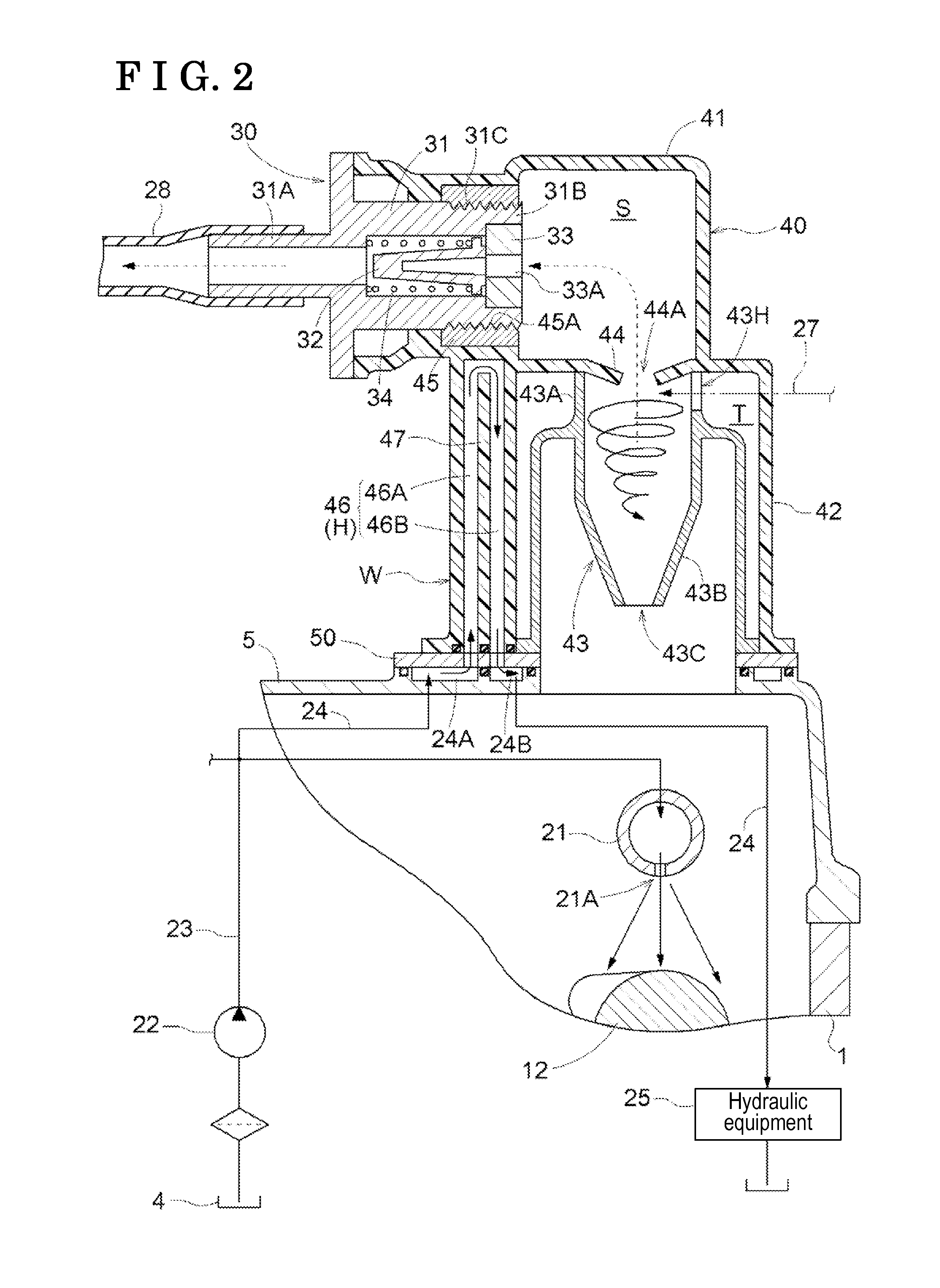
[0027]FIG. 1 and FIG. 2 illustrate an engine to be provided at, for example, a vehicle. The engine includes a cylinder head 1, a cylinder block 2, a crankcase 3 and an oil pan 4 which are placed up and down to be arranged one above another, and are connected to one another, and a head cover 5 is provided at an upper portion of the cylinder head 1.

[0028]A crankshaft 6 is rotatably supported inside of the crankcase 3 and plural pistons 7 are slidably fitted into plural cylinder bores formed at the cylinder block 2. These pistons 7 and the crankshaft 6 are connected to each other with connecting rods 8.

[0029]The cylinder head 1 is provided with an air intake valve 9 and an exhaust valve 10 to be able to open and close. At upper positions of the air intake valve 9 and the air exhaust valve 10, an intake cam shaft 11 and an exhaust cam shaft 12, which are in postur...


PUM


Abstract

A blow-by gas recirculation apparatus which can release freezing of a PCV valve in a short period of time is obtained with a simple configuration. The blow-by gas recirculation apparatus is provided with the PCV valve at a case member of a gas space portion to which blow-by gas is sent in a manner that the PCV valve penetrates through the case member and a return path supplying the blow-by the gas, which is from the PCV valve, to an induction system of an engine. A heating portion to which part of oil lubricating the engine is supplied and thus which heats the PCV valve with heat of the oil is formed.

Description

TECHNICAL FIELD[0001]The present invention relates to a blow-by gas recirculation apparatus, and specifically relates to a measure against freezing of a PCV valve sending out blow-by gas, which occurs at an engine, from the engine.BACKGROUND ART[0002]Blow-by gas including unburnt gas generated at an engine includes moisture. For example, in a case where the engine stops in a cold district, the moisture of the blow-by gas remaining inside a PCV valve may freeze. Thus, technique related to a measure against the freezing of the PCV valve includes technique, for example, presented in Patent document 1, wherein a freeze detection portion detecting presence / absence of the freezing of the PCV valve and a freeze release portion releasing the freezing of the PCV valve are described.[0003]That is, in Patent document 1, a blow-by gas recirculation apparatus which sends the blow-by gas to a surge tank for air-intake via the PCV valve provided at a head cover is configured. A thermal heater is p...

Claims


Application Information

Patent Timeline
IPC IPC(8): F01M13/02F01M13/04F02F7/00
CPCF01M13/02F01M13/04F02F7/0095F01M13/0011F01M2013/0027F02F7/006F01M9/101F01M13/0416F01M2013/0427F01M2013/0472F01M13/00
Inventor KIRA, NAOKINISHIGAKI, ATSUSHIINOKUCHI, TAKAHIRO
Owner AISIN SEIKI KK
Learn More