
Range-change transmission of a motor vehicle

Active Publication Date: 2015-12-10
ZF FRIEDRICHSHAFEN AG
View PDF7 Cites 4 Cited by
  • Summary
  • Abstract
  • Description
  • Claims
  • Application Information

AI Technical Summary

Benefits of technology

The present invention proposes a group transmission for a motor vehicle that includes a multi-stage main transmission and a range group in driving connection downstream from the main transmission. The shifting mechanisms in the range group are simpler and can be extended by a shiftable gear ratio stage for a driving range of medium driving speeds. The range group is formed of two planetary gearsets coupled in a way that only one of the shifting clutches is needed to engage the gear ratio stages for the two speed ranges and the reverse driving range, making the shifting mechanism simpler. A driving range for medium speeds can be easily engaged by connecting the planetary carrier of the first planetary gearset and the ring gear of the second planetary gearset in a rotationally fixed manner with a shifting clutch. The engagement of the driving range for higher speeds can be achieved by connecting the planetary carrier of the first planetary gearset to the sun gear of the second planetary gearset with the second shifting clutch.

Problems solved by technology

However, since many shifts in a group transmission require gearshifts in a number of partial transmissions and therefore take place with relatively complex sequences, most known group transmissions are shifted either in a partially automated or fully automated manner.
Thus, the disadvantage of the range group design known from EP 1 825 168 B1 is the complicated structure in particular of the second shifting element and the need for two shift actuators for the simultaneous actuation of the two shifting elements.

Method used


Image

  • Range-change transmission of a motor vehicle
  • Range-change transmission of a motor vehicle
  • Range-change transmission of a motor vehicle

Examples


Embodiment Construction

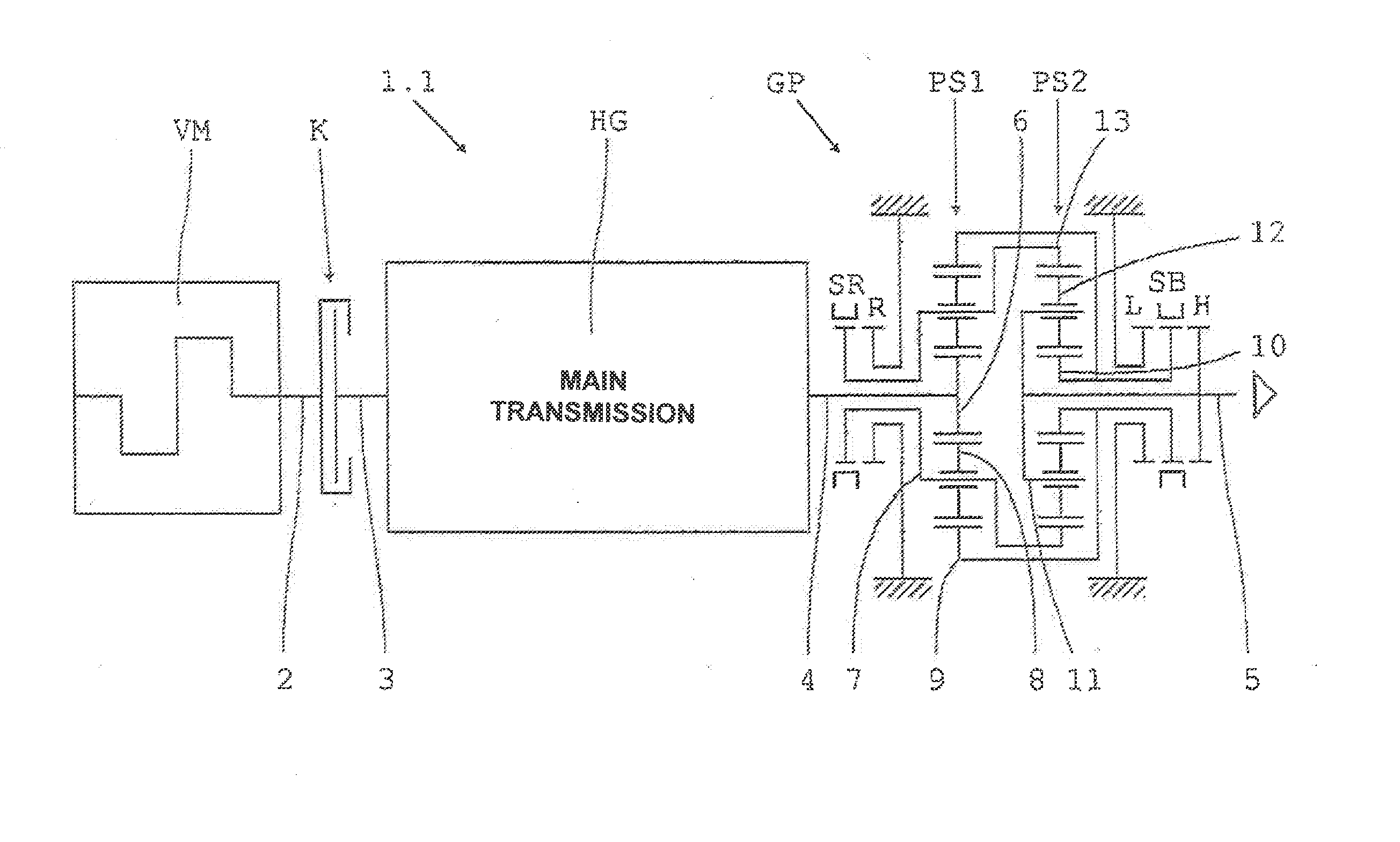
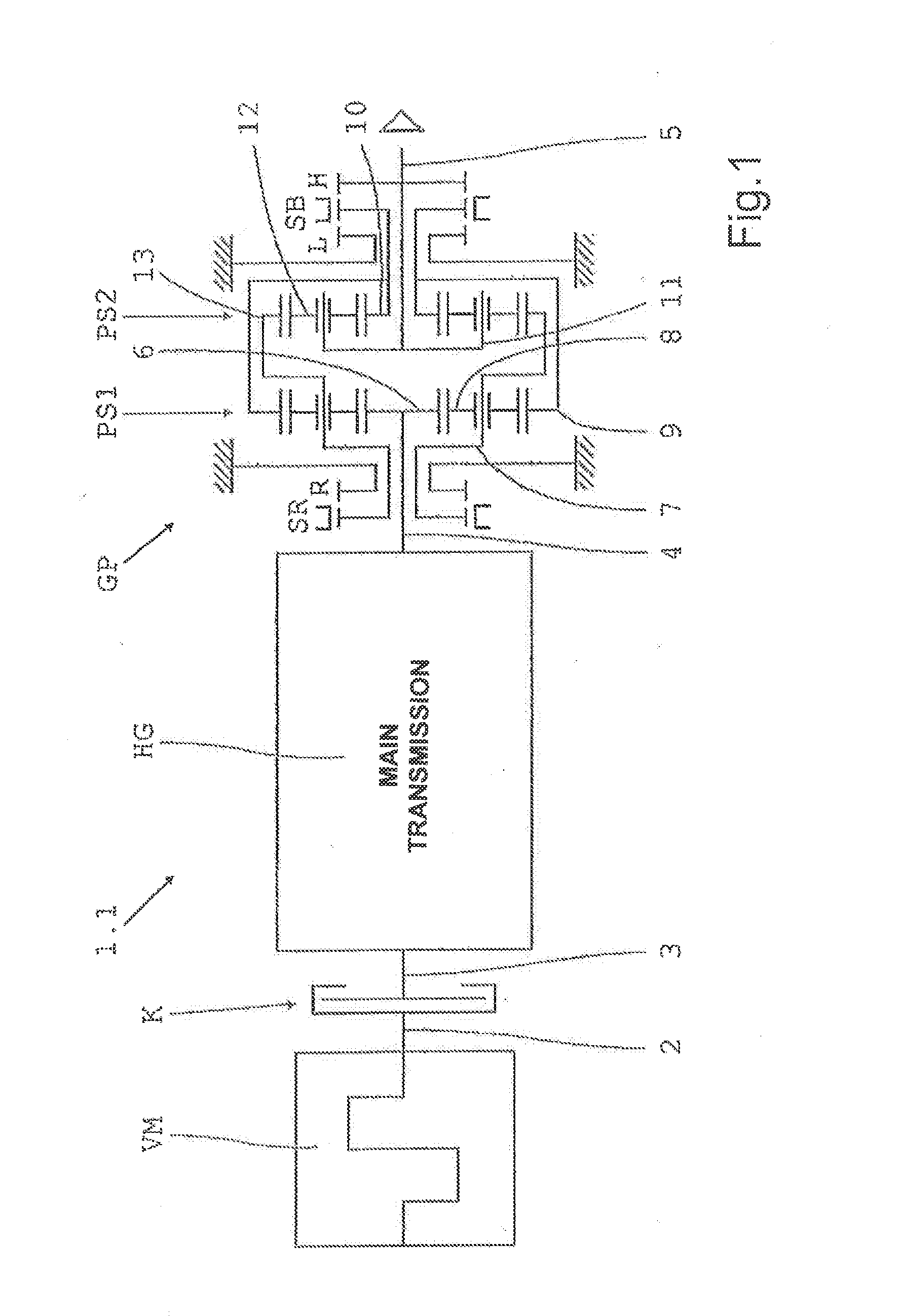
[0048]A group transmission 1.1 illustrated in schematic form in FIG. 1 comprises a multi-stage main transmission HG (not shown in greater detail) and a range group GP in drive connection downstream from the main transmission HG. The main transmission HG has an input shaft 3 and on its output side an output shaft 4. The input shaft 3 can be connected by way of a friction clutch K to the driveshaft 2 of a drive engine VM in the form of an internal combustion engine. The range group GP is positioned between the main shaft 4 and an output shaft 5, which (in a manner not shown) is in driving connection with an axle drive such as an axle differential or a transfer box.

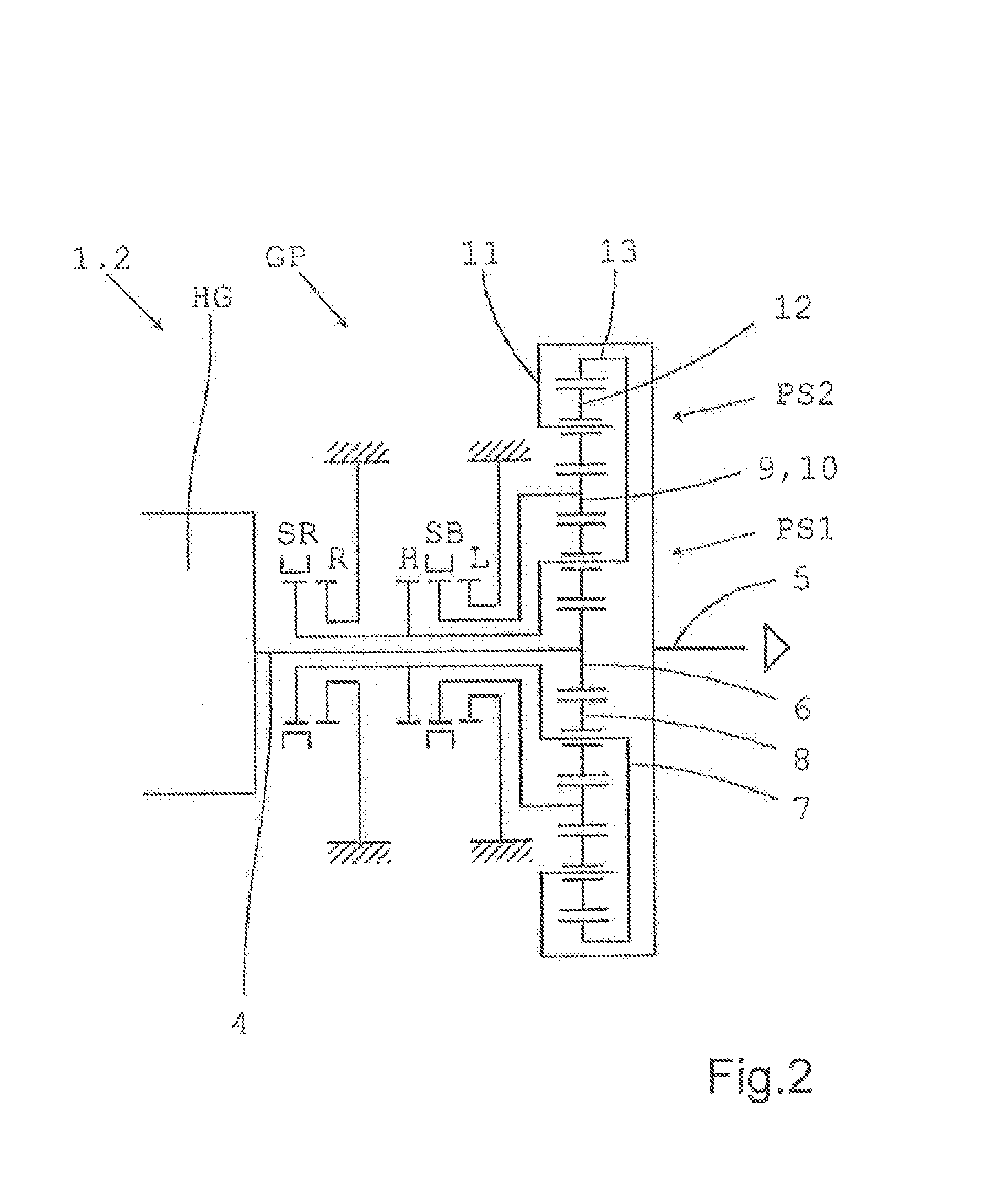
[0049]The range group GP is of planetary design and comprises two mutually coupled planetary gearsets PS1, PS2, each respectively having a sun gear 6, 10, a planetary carrier 7, 11 that supports a number of planetary wheels 8, 12, and a ring gear 9, 13. In the present case the two planetary gearsets PS1, PS2 of the range gro...


PUM


Abstract

A group transmission of a motor vehicle having a main transmission and a downstream range group. The range group has two gear steps for different speed ranges and a reversing step for reverse driving. The range group has two planetary gearsets, each with a planet carrier, a sun and ring gears. To engage a driving range for lower speeds, the sun gear of the second gearset and the ring gear of the first gearset are locked to the housing by a first clutch. To engage a driving range for higher speeds, two respective elements of the two gearsets can be connected to one another, in a rotationally fixed manner, by a second clutch. To engage a reversing driving range, the planet carrier of the first gearset and the ring gear of the second gearset are locked relative to the housing by a third clutch.

Description

[0001]This application is a National Stage completion of PCT / EP2014 / 050109 filed Jan. 7, 2014, which claims priority from German patent application serial no. 10 2013 202 045.7 filed Feb. 7, 2013.FIELD OF THE INVENTION[0002]The invention concerns a group transmission for a motor vehicle, for example a heavy goods vehicle, comprising a main transmission with at least one input shaft and on the output side a main shaft, and with at least one range group connected downstream from the main transmission and arranged between the main shaft and an output shaft, wherein the range group is of planetary design with at least two shiftable gear ratio stages for different speed ranges and one shiftable reversing stage for a reverse driving range.BACKGROUND OF THE INVENTION[0003]Group transmissions with a multi-stage main transmission and at least one range group in drive connection downstream from the main transmission have long been known and are preferably used in heavy good vehicles. Often, t...

Claims


Application Information

Patent Timeline
IPC IPC(8): F16H37/04
CPCF16H37/046F16H2037/049F16H2200/2007F16H2200/0082F16H2200/0078
Inventor KALTENBACH, JOHANNESLUBKE, ECKHARDTWECHS, MICHAEL
Owner ZF FRIEDRICHSHAFEN AG
Learn More