Air conditioner with selective filtering for air purification

a technology of air conditioner and selective filtering, which is applied in the field of split-system air conditioner or heat pump system, can solve the problems of not providing substantial air purification through filtering and not being effective in removing most, and achieves the effect of saving energy use and reducing the degree of filtration of air

Inactive Publication Date: 2015-12-10
WHIRLPOOL CORP
View PDF10 Cites 36 Cited by
  • Summary
  • Abstract
  • Description
  • Claims
  • Application Information

AI Technical Summary

Benefits of technology

[0006]In a preferred embodiment of the invention, the cabinet includes one or more movable dampers or movable filters positioned in the flow path between the air inlet and the outlet for selectively filtering contaminants from the air to provide a greater or lesser degree of filtration of the air. The movable filters include sliding and / or pivot mounting structure which may accommodate stacking multiple filters with different filtering characteristics. The system may operate in a filtering only mode with no cooling or heating, a cooling or heating only mode with no filtering, or a combination of cooling / heating and selective filtering.
[0007]In another aspect of the invention, the indoor unit air intake is primarily or wholly from the louvers located at the bottom section of the indoor unit instead of from the louvers located on the upper section of the indoor unit as in conventional split air conditioners. Intaking air from the lower portion of the space to be cooled has real energy use saving benefits since the warm air close to the ceiling of the space being cooled is left mostly undisturbed and focus is upon cooling the air where the occupants are located.

Problems solved by technology

Such systems provide cooling frequently for a single room or multiple rooms, however, they do not provide substantial air purification by filtering or the like other than a simple screen filter which is not effective for removal of most pollutants.

Method used


Image

  • Air conditioner with selective filtering for air purification
  • Air conditioner with selective filtering for air purification
  • Air conditioner with selective filtering for air purification

Examples


Embodiment Construction

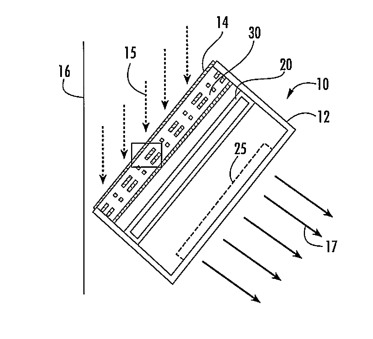
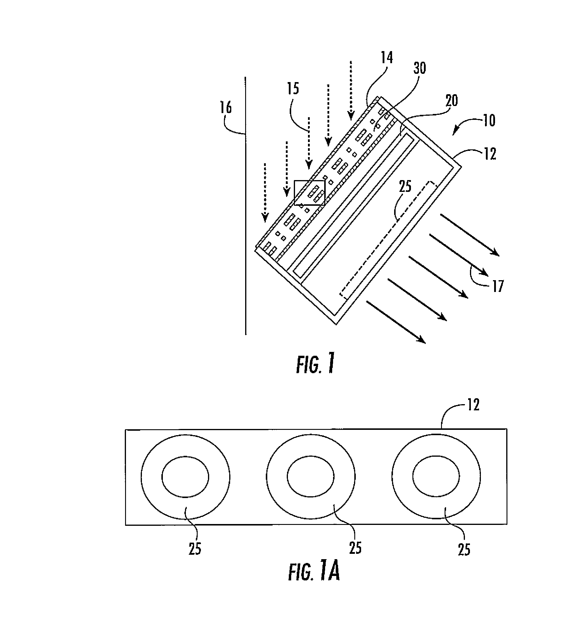
[0040]Referring initially to FIGS. 1 and 1A, they illustrate one embodiment of the present invention, in which a split air conditioning system includes an indoor air conditioner unit 10 with a cabinet 12, which has a rear air inlet grill 14 for receiving inlet air to be conditioned, as shown by arrows 15. As used herein, air conditioning is intended to encompass both cooling of air or, in a heat pump installation, either cooling or heating of air with an indoor evaporator. The cabinet 12 is typically mounted to a support wall 16 of a building structure using suitable brackets. In floor-mounted installations, it will rest on the floor of a room. Within cabinet 12, there is positioned a micro channel or a fin-and-tube type heat exchanger which is a flat evaporator 20 conventionally coupled to an outside compressor / condenser unit for receiving a high pressure refrigerant liquid through a capillary tube or expansion valve fluidically coupled to the evaporator for cooling the input air 1...


PUM

PropertyMeasurementUnit
movementaaaaaaaaaa
thermal stratificationaaaaaaaaaa
pressureaaaaaaaaaa

Abstract

A split air conditioner has a cabinet with a fan and evaporator for mounting within a structure. The cabinet includes one or more movable dampers or movable filters positioned in the flow path between the air inlet and the outlet for selectively filtering contaminants from the air to provide a greater or lesser degree of filtration of the air. The movable filters include sliding and/or pivot mounting structure which may accommodate stacking multiple filters with different filtering characteristics. The system may operate in a filtering only mode with no cooling, a cooling only mode with no filtering, or a combination of cooling and selective filtering.

Description

CROSS-REFERENCE TO RELATED APPLICATIONS[0001]This application is a continuation-in-part of U.S. application Ser. No. 14 / 644,510 entitled AIR CONDITIONER WITH SELECTIVE FILTERING FOR AIR PURIFICATION, filed on Mar. 11, 2015, which claims priority under 35 U.S.C. §119(e) and the benefit of U.S. Provisional Application No. 62 / 010,088 entitled SPLIT SYSTEM OUTDOOR AIR UNIT, filed on Jun. 10, 2014, and 62 / 064,181 entitled SPLIT SYSTEM AIR CONDITIONER / HEAT PUMP WITH DUAL HUB FAN CONDENSING UNIT AND ENHANCED COMPRESSOR COOLING, filed on Oct. 15, 2014. This application is also a continuation-in-part of U.S. application Ser. No. 14 / 644,553 entitled AIR CONDITIONER WITH SELECTIVE FILTERING FOR AIR PURIFICATION, filed on Mar. 11, 2015, which claims priority under 35 U.S.C. §119(e) and the benefit of U.S. Provisional Application Nos. 62 / 010,088 entitled SPLIT SYSTEM OUTDOOR AIR UNIT, filed on Jun. 10, 2014, and 62 / 064,181 entitled SPLIT SYSTEM AIR CONDITIONER / HEAT PUMP WITH DUAL HUB FAN CONDENS...

Claims


Application Information

Patent Timeline
Patent Type & Authority Applications(United States)
IPC IPC(8): F25B39/00B23P15/26F25B49/00F24F1/0073F24F1/0059
CPCF25B39/00F25B49/00Y10T29/49361F25B39/02B23P15/26F24F13/28F24F2110/70F24F11/65F24F2110/72F24F2110/64F24F8/108F24F8/10Y02B30/70F24F1/0059F24F1/0073Y02A50/20
Inventor CUR, NIHAT O.GUARINO, JAMES C.L.KENDALL, JAMES W.KUEHL, STEVEN J.
Owner WHIRLPOOL CORP
Why Eureka
Try Eureka