Storage system, computer system and data migration method

a technology of storage system and data migration, applied in the field of storage system and computer system data migration methods, can solve the problem of taking a long time to migrate all the data, and achieve the effect of high access frequency, low access frequency, and large capacity

Active Publication Date: 2015-12-10
HITACHI LTD
View PDF0 Cites 42 Cited by
  • Summary
  • Abstract
  • Description
  • Claims
  • Application Information

AI Technical Summary

Benefits of technology

[0011]According to the storage system of the present invention, data migration is performed based on the “PULL” type data migration, prioritizing the files having higher access frequencies, so that the occurrence of delay of responses can be suppressed during operation of files by the users. Furthermore, by performing data migration based on the “PUSH” type data migration by prioritizing migration of files having a low access frequency and a large capacity, it becomes possible to enhance the data migration efficiency and to reduce the data migration time. The problems, configurations and effects other than those described above will become apparent from the following description of the preferred embodiments.

Problems solved by technology

Generally, in such cases, a large amount of data is accumulated in the existing file storage subsystem being the migration source, and it takes a long time to migrate all the data.

Method used


Image

  • Storage system, computer system and data migration method
  • Storage system, computer system and data migration method
  • Storage system, computer system and data migration method

Examples


embodiment 1

Computer System Configuration

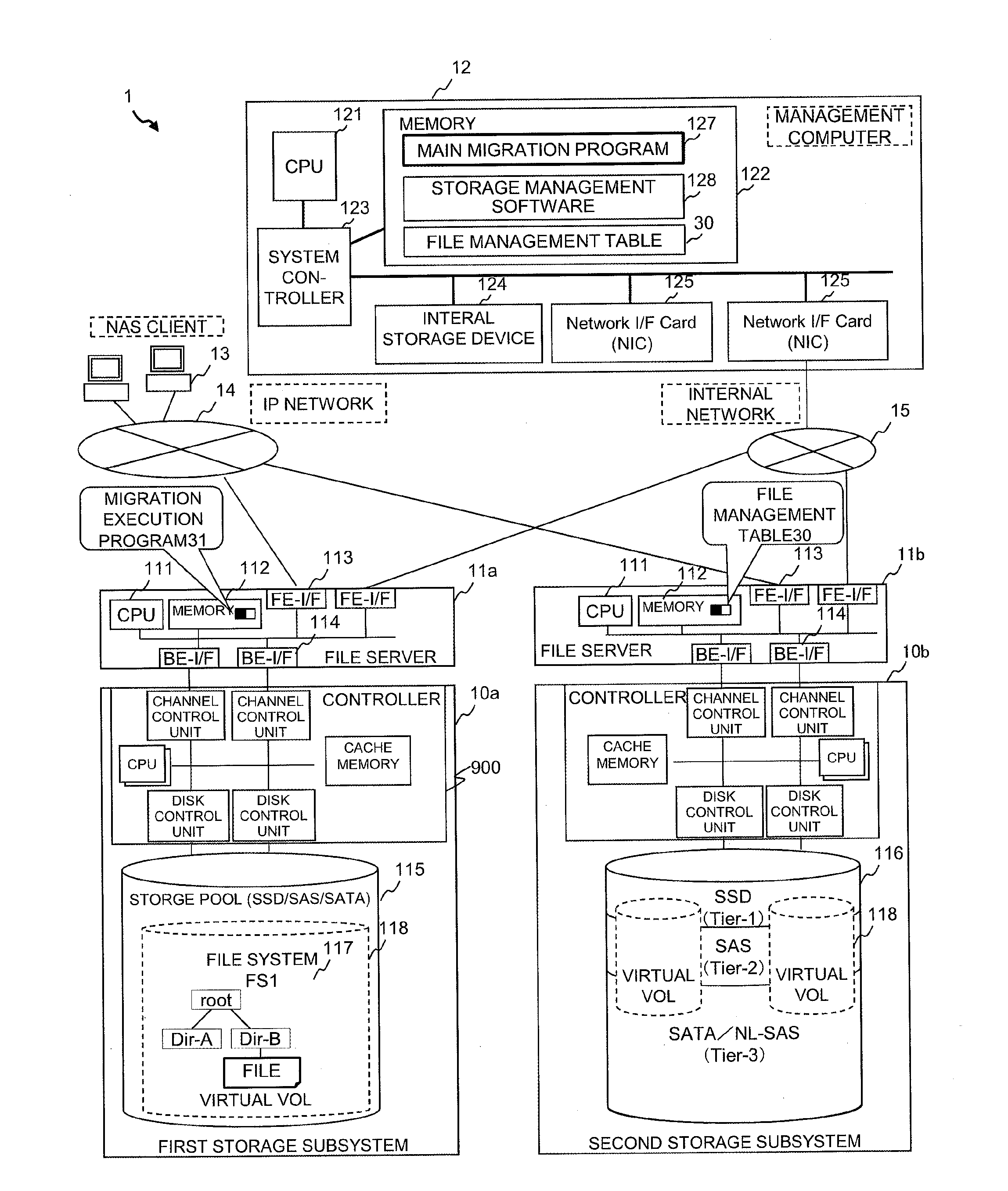
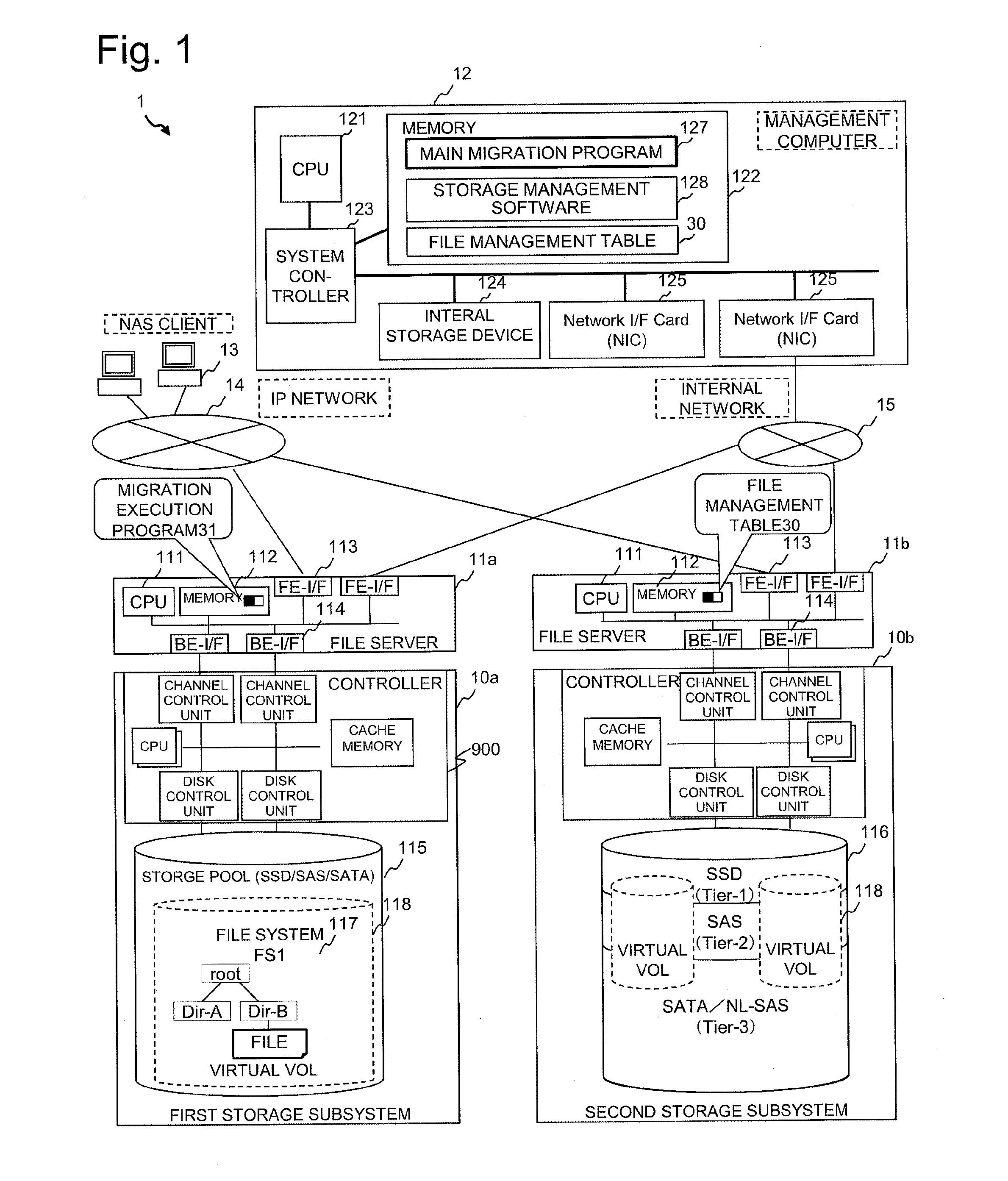
[0028]FIG. 1 is a block diagram of major hardware included in a computer system according to the present embodiment. A computer system 1 has a first storage subsystem (hereinafter referred to as migration source storage subsystem) 10a, a second storage subsystem (hereinafter referred to as migration destination storage subsystem) 10b, a first file server (hereinafter referred to as migration source file server) 11a for controlling the migration source storage subsystem 10a, a second file server (migration destination file server) 11b for controlling the migration destination storage subsystem 10b, a management computer 12 for managing the migration source file server 11a and the migration destination file server 11b, and a NAS client computer (hereinafter referred to as client computer) 13, which are coupled via an IP network 14 or an internal network 15. The migration source storage subsystem 10a and the migration destination storage subsystem 10b can b...

embodiment 2

HYBRID Migration Processing

[0151]FIG. 13 is a flowchart showing the processing performed by performing the “PUSH” type migration in the migration source file server and the “PULL” type migration in the migration destination file server in combination. In the “PUSH” type migration, when a migrated file is updated in the migration source file server 11a during migration of data to the migration destination file server 11b, the migration source file server 11a must transmit the file again to the migration destination file server 11b, so that the data transfer efficiency (data migration efficiency) is deteriorated. Therefore, the files having no accesses (including files having a low access frequency) are copied from the migration source file server 11a having a small overhead via a “PUSH” type migration to the migration destination file server 11b, and at the point of time when the copying process is completed, the remaining files other than the file having no accesses are migrated tog...


PUM


Abstract

The present invention provides a storage subsystem capable of realizing efficient data migration and high access performance. During migration of data between storage subsystems, data migration methods are selected between a “PUSH” type and a “PULL” type method based on a data migration policy set in advance to perform data migration processes. An access characteristics of a file and a folder storing the file are determined based on a file access frequency or a final access date and time information in a migration source storage subsystem, and the migration order of a file group determined to have a high possibility of being accessed during data migration is changed between the “PUSH” type and the “PULL” type.

Description

TECHNICAL FIELD[0001]The present invention relates to storage systems, computer systems and data migration methods.BACKGROUND ART[0002]When replacing file storage subsystems capable of storing electronic files used for businesses and sharing the same using a network, it is necessary to migrate the data (files, directory structures and the like) stored in existing file storage subsystems to a new file storage subsystem.[0003]Generally, in such cases, a large amount of data is accumulated in the existing file storage subsystem being the migration source, and it takes a long time to migrate all the data. Therefore, in the prior art, a technique called online migration is known, where file operation and the like can be performed successively without stopping operation during the data migration processing, as taught in Patent Literatures 1 and 2.CITATION LISTPatent Literature[0004][PTL 1] United States Patent Application Laid-Open No. 2005 / 0256898 (Japanese Patent Application Laid-Open N...

Claims


Application Information

Patent Timeline
Patent Type & Authority Applications(United States)
IPC IPC(8): G06F17/30
CPCG06F17/302G06F17/30091G06F17/30174G06F16/119G06F16/122G06F16/178G06F16/13G06F16/1827
Inventor KISHIMOTO, SATORUNAKATANI, YOJISUNADA, YOJI
Owner HITACHI LTD
Why Eureka
Try Eureka