Noise suppression cable

a technology of noise suppression and cable, which is applied in the direction of cables, insulated conductors, conductors, etc., can solve the problem of not sufficiently suppressing the electromagnetic wave noise emitted by the cable, and achieve the effect of reducing electromagnetic wave noise and being easy to manufactur

Active Publication Date: 2015-12-10
HITACHI METALS LTD
View PDF3 Cites 6 Cited by
  • Summary
  • Abstract
  • Description
  • Claims
  • Application Information

AI Technical Summary

Benefits of technology

[0020]According to one embodiment of the invention, a noise suppression cable can be provided that is capable of reducing the electromagnetic wave noise in a wide band and is easy to manufacture.

Problems solved by technology

The noise suppression cable disclosed in JP-A-2004-158328 may not sufficiently suppress the electromagnetic wave noise emitted from the cable due to the mixture ratio of the magnetic powder.

Method used


Image

  • Noise suppression cable
  • Noise suppression cable
  • Noise suppression cable

Examples


first embodiment

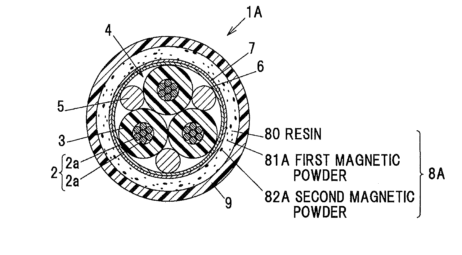
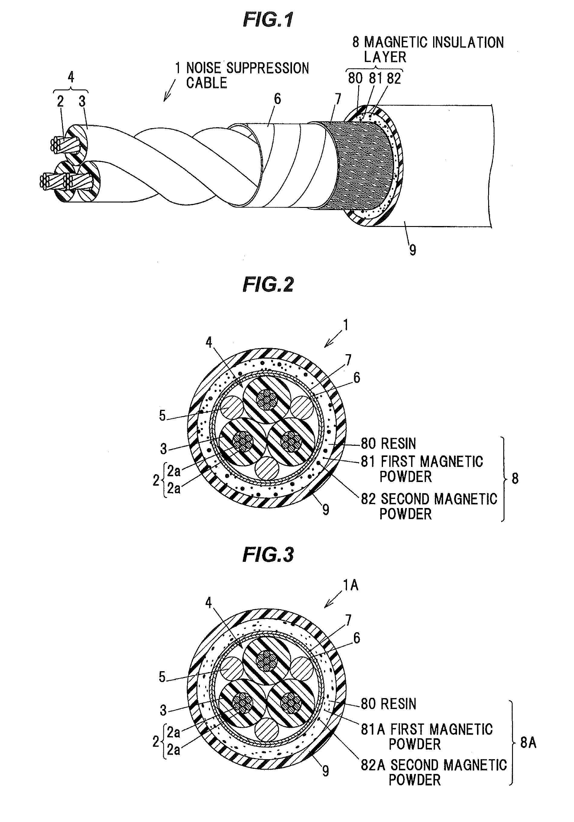
[0027]FIG. 1 is a perspective view showing a general configuration of a noise suppression cable in the first embodiment of the invention. FIG. 2 is a cross sectional view showing the noise suppression cable shown in FIG. 1. FIG. 3 is a cross sectional view showing a modification of the noise suppression cable shown in FIG. 1. An illustration of inclusions 5 is omitted in FIG. 1.

[0028]A noise suppression cable 1 shown in FIGS. 1 and 2 is provided with plural insulated wires 4 (three in the first embodiment) each formed by covering a conductor wire 2 with an insulation 3, a resin tape layer 6 wound around the plural insulated wires 4 with inclusions 5 interposed therebetween, a shield layer 7 provided around the resin tape layer 6, a magnetic insulation layer 8 provided around the shield layer 7 and a sheath 9 as an insulating protective layer formed of a resin, etc., and provided around the magnetic insulation layer 8.

[0029]The conductor wire 2 is formed by twisting plural thin metal...

second embodiment

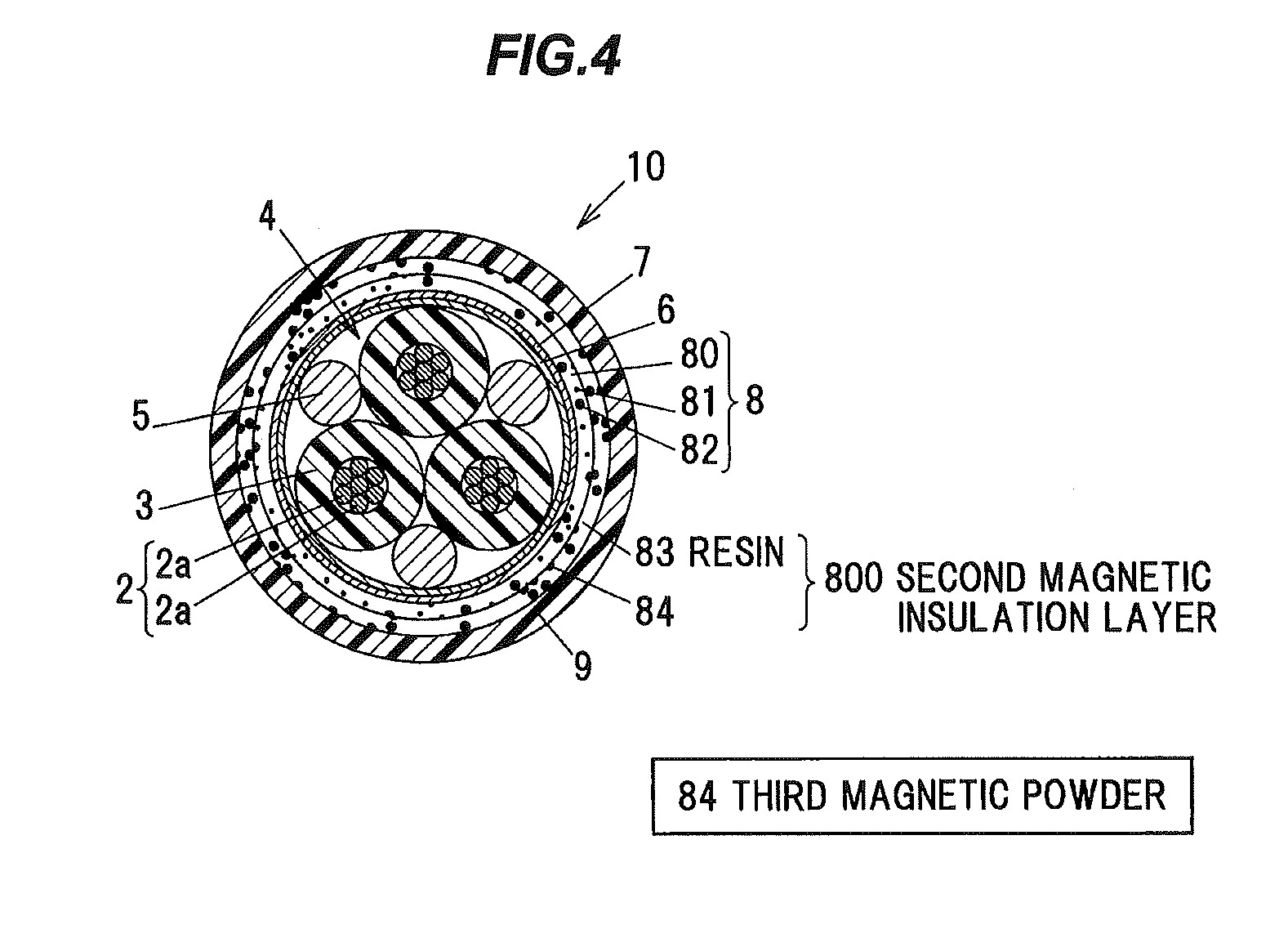
[0043]FIG. 4 is a cross sectional view showing a noise suppression cable in the second embodiment of the invention.

[0044]A noise suppression cable 10 shown in FIG. 4 is different from the noise suppression cable 1 in the first embodiment of the invention in that the periphery of the magnetic insulation layer 8 is covered with a second magnetic insulation layer 800 which is formed of a mixture of a resin 83 as an insulating material and the third magnetic powder 84 having different frequency characteristics from the first and second magnetic powders 81 and 82. Although only the third magnetic powder 84 is mixed to the resin 83 in the second embodiment, two or more types of magnetic powders having different frequency characteristics from the first and second magnetic powders 81 and 82 may be mixed.

[0045]The material of the resin 83 may be same as or different from the material of the resin 80.

[0046]As the third magnetic powder 84, it is possible to use magnetic powder which has a rela...


PUM

PropertyMeasurementUnit
thicknessaaaaaaaaaa
diameteraaaaaaaaaa
diameteraaaaaaaaaa

Abstract

A noise suppression cable includes a conductor wire, and a magnetic insulation layer on a periphery of the conductor wire. The magnetic insulation layer includes an insulating material and two or more types of magnetic powders that have different frequency characteristics from each other.

Description

[0001]The present application is based on Japanese patent application No. 2014-119904 filed on Jun. 10, 2014, the entire contents of which are incorporated herein by reference.BACKGROUND OF THE INVENTION[0002]1. Field of the Invention[0003]The invention relates to a noise suppression cable.[0004]2. Description of the Related Art[0005]An electromagnetic shielded cable capable of reducing electromagnetic wave noise over a wide band has been proposed. The electromagnetic shielded cable is configured such that a shielding member interposed between a conductor and an insulation cover covering the conductor is composed of three layers, a layer formed of a synthetic rubber mixed with a high-frequency magnetic powder, a layer formed of a synthetic rubber mixed with an intermediate-frequency magnetic powder and a layer formed of a synthetic rubber mixed with a low-frequency magnetic powder (see e.g. JP-A-H11-329089).[0006]Also, a noise suppression cable has been proposed in which an insulate...

Claims


Application Information

Patent Timeline
Patent Type & Authority Applications(United States)
IPC IPC(8): H01B11/10
CPCH01B11/1083
Inventor SUMI, YOSUKECHIWATA, NAOFUMIAKIMOTO, KATSUYANAKATANI, KATSUTOSHIKOMURO, HIROSHIAJIMA, KENJIOKIKAWA, HIROSHIMUTO, YASUHARU
Owner HITACHI METALS LTD
Why Eureka
Try Eureka