Electrostatic coater and electrostatic coating method

a technology of electrostatic coating and electrostatic coating, which is applied in the direction of electrostatic spraying apparatus, spraying power supply, burner, etc., can solve the problems of increasing the risk of spark discharge between the electrostatic coating and the workpiece, increasing the amount of wasteful discharge outside, and reducing the high voltage applied to the electrostatic coating

Active Publication Date: 2015-12-17
CARLISLE FLUID TECH RANSBURG JAPAN KK
View PDF9 Cites 1 Cited by
  • Summary
  • Abstract
  • Description
  • Claims
  • Application Information

AI Technical Summary

Benefits of technology

[0023]Here, the “neutralization” in the present invention is not limited to a meaning in which the charge existing in the electrostatic coater immediately after the running stop becomes “zero”. The “neutralization” in the present invention includes a meaning in which the charge is reduced to a charge amount where a spark discharge accident by the electrostatic coater immediately after the running stop can be avoided.

Problems solved by technology

However, the means for improving the coating efficiency as described above bring a tendency to increase a risk of the occurrence of the spark discharge between the electrostatic coater and the workpiece.
That is, lowering the value of the bleeder resistance causes an increase in power amount wastefully discharged outside from the power supplied to the electrostatic coater.
This means that an absolute value of a high voltage applied to the electrostatic coater is reduced to cause a decrease in coating quality and a decrease in coating efficiency.
Thus, there occurs a problem that a power amount supplied to the electrostatic coater needs to be increased in order to maintain the same absolute value of the high voltage applied to the electrostatic coater as that of a conventional case.

Method used


Image

  • Electrostatic coater and electrostatic coating method
  • Electrostatic coater and electrostatic coating method
  • Electrostatic coater and electrostatic coating method

Examples


first embodiment

FIGS. 1 to 3

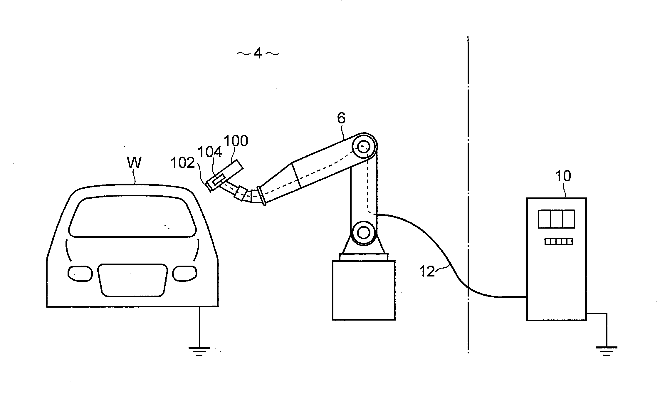
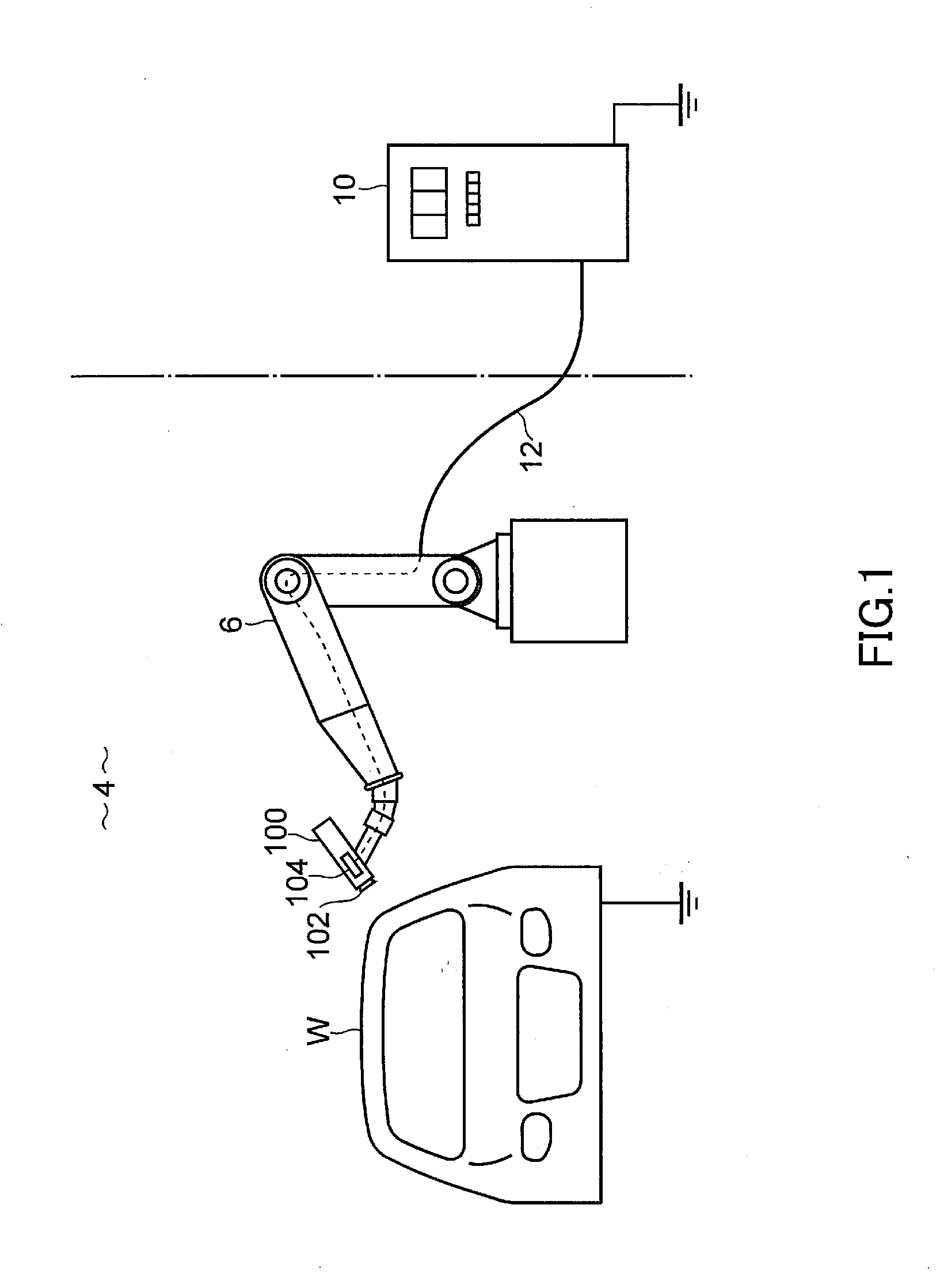
[0032]By reference to FIG. 1, reference numeral 4 denotes a coating booth. An explosion-proof space is formed by the coating booth 4. A plurality of coating robots 6 are installed in the coating booth 4. An electrostatic coater 100 of a first embodiment is mounted to a distal end of an arm of each of the coating robots 6. Electrostatic coating is given to an automobile W by the coating robots 6. The automobile W is an object to be coated (a workpiece) fed into the coating booth 4.

[0033]A controller 10 is installed outside the coating booth 4. The controller 10 and the electrostatic coater 100 are connected via a low-voltage (LV) cable 12. A high voltage of the electrostatic coater 100 is controlled by the controller 10. The controller 10 includes a safety circuit, which stops running of the electrostatic coater 100 when detecting that the electrostatic coater 100 is in a dangerous state. Since the above configuration including the safety circuit is conventionally well kn...

second embodiment

FIGS. 5 and 6

[0062]FIG. 5 shows a diagram for explaining an outline of an electrostatic coater 200 of a second embodiment. Although the electrostatic coater 100 of the first embodiment employs the configuration in which the charge retained in the distal end portion of the electrostatic coater 100 is neutralized by supplying the voltage of reverse polarity (positive polarity) to the rotary atomizing head 102 as described above, the electrostatic coater 200 of the second embodiment (FIG. 5) employs a configuration in which the charge remaining in the distal end portion of the electrostatic coater 200 is neutralized by supplying air charged with reverse polarity (positive polarity) to the electrostatic coater 200.

[0063]In a description of the electrostatic coater 200 of the second embodiment, the same elements as those of the electrostatic coater 100 of the above first embodiment are assigned the same reference numerals, and a description thereof is omitted.

[0064]The electrostatic coat...


PUM


Abstract

A charge remaining in an electrostatic coater when power supply to the electrostatic coater is stopped is neutralized at an early stage.A rotary atomizing head 102 receives a high voltage of negative polarity from a cascade 104. An electrostatic coater 100 further includes a second high-voltage generator 110 that generates a high voltage of positive polarity. The second high-voltage generator 110 is composed of a Cockcroft-Walton circuit. The Cockcroft-Walton circuit is composed of diodes and capacitors. A high voltage of the electrostatic coater 100 is controlled by a controller 10. Immediately after running of the electrostatic coater 100 is stopped by stopping power supply to the cascade 104, power is supplied to the second high-voltage generator 110. The high voltage of positive polarity generated by the second high-voltage generator 110 is supplied to the rotary atomizing head 102 for a predetermined time period.

Description

BACKGROUND OF THE INVENTION[0001]The present invention relates to an electrostatic coater, and typically relates to safety measures when a coater abnormally approaches a workpiece (an object to be coated).[0002]For example, electrostatic coaters are generally used for coating of automobiles. The coating of automobiles has been robotized. A coating robot is installed in a coating booth. The coating booth is an explosion-proof space. The coating robot is connected to a controller installed outside the coating booth via a cable. An electrostatic coater of the coating robot is controlled based on an instruction from the controller.[0003]Patent Literature 1 (Japanese Patent Laid-Open No. 2012-50949) discloses an electrostatic coater in which a high-voltage generator is incorporated. This type of electrostatic coater includes a bleeder resistance for safety measures in addition to the incorporated high-voltage generator, and the electrostatic coater is grounded via the bleeder resistance ...

Claims


Application Information

Patent Timeline
Patent Type & Authority Applications(United States)
IPC IPC(8): B05B5/053B05B13/04B05B5/04
CPCB05B5/053B05B13/0431B05B5/04B05B5/0407B05B5/043B05B12/08B05B13/0452B05B5/025B05B5/0255B05B14/42
Inventor IWASE, MASATOSHIOTA, NAOKIOKAMOTO, KENJI
Owner CARLISLE FLUID TECH RANSBURG JAPAN KK
Why Eureka
Try Eureka