Work vehicle and control method for same

a technology for working vehicles and control methods, applied in mechanical machines/dredgers, analogue processes for specific applications, instruments, etc., can solve problems such as difficulty in raising buckets, excessive and work becomes difficult to perform, so as to reduce the load on work implements that is excessive, simple operation, and simple operation

Active Publication Date: 2015-12-17
KOMATSU LTD
View PDF11 Cites 20 Cited by
  • Summary
  • Abstract
  • Description
  • Claims
  • Application Information

AI Technical Summary

Benefits of technology

[0009]The required tractive force is reduced to a value below a value corresponding to the operating amount of the accelerator operating member during excavating in the work vehicle according to the present exemplary embodiment. The output torque of the electric motor is determined in response to the reduced required tractive force. As a result, the tractive force of the vehicle is reduced to a value below the value corresponding to the operating amount of the accelerator operating member to suppress a load on the work implement from becoming excessive. As a result, a balance can be achieved between the tractive force of the vehicle and the driving power of the work implement with a simple operation in the work vehicle according to the present exemplary embodiment.
[0010]The tractive force limiting unit preferably corrects the operating amount of the accelerator operating member to a value smaller than the actual operating amount while the vehicle is excavating. The transmission requirement determination unit determines the required tractive force on the basis of the corrected operating amount of the accelerator operating member. In this case, the tractive force limiting unit corrects the operating amount of the accelerator operating member whereby the tractive force of the vehicle is reduced. As a result, the tractive force of the vehicle can be reduced with a simple control.
[0011]The tractive force limiting unit preferably reduces the required tractive force to a value below the value corresponding to the operating amount of the accelerator operating member while the vehicle is excavating and when a discharge pressure of the hydraulic pump is greater than a predetermined threshold. The discharge pressure of the hydraulic pump fluctuates in response to the size of the load on the work implement. Therefore, by reducing the required tractive force when the discharge pressure of the hydraulic pump is greater than the predetermined threshold, the tractive force can be reduced when a large load is applied to the work implement. As a result, the balance between the tractive force of the vehicle and the driving power of the work implement can be achieved in a suitable manner.
[0014]In this case, the engine required horsepower is determined as a value required for achieving the work implement required horsepower even when the tractive force limiting unit reduces the required tractive force. Therefore, the required work implement required horsepower can be assured even when the tractive force limiting unit reduces the required tractive force. For example, when the tractive force is reduced due to the command throttle for the engine being limited as in a conventional work vehicle, the driving power of the hydraulic pump is reduced due to a reduction in the engine rotation speed. As a result, it is difficult to assure a required work implement required horsepower. In comparison to the conventional work vehicle, a required work implement required horsepower can be assured easily in the work vehicle according to the exemplary present embodiment.
[0017]The required tractive force is reduced to a value below the value corresponding to the operating amount of the accelerator operating member during excavating in the control method for the work vehicle according to the present exemplary embodiment. The output torque of the electric motor is determined in response to the reduced required tractive force. As a result, the tractive force of the vehicle is reduced to a value below the value corresponding to the operating amount of the accelerator operating member to suppress a load on the work implement from increasing excessively. As a result, a balance can be achieved between the tractive force of the vehicle and the driving power of the work implement with a simple operation in the control method for the work vehicle according to the present exemplary embodiment.
[0018]According to exemplary embodiments of the present invention, a work vehicle that is able to maintain balance between the tractive force of the vehicle and the driving power of the work implement with a simple operation, and a control method for the same can be provided.

Problems solved by technology

Therefore, if the tractive force increases and the force for pushing the bucket increases excessively, it becomes difficult to raise the bucket.
In this way, the load on the work implement becomes too large when the tractive force during the excavating work becomes excessive.
In this case, there is a problem that work becomes difficult to perform or fuel consumption is reduced.
However, it is difficult to maintain a balance between the tractive force of the vehicle and the driving power of the work implement when controlling the engine as mentioned above in this hybrid-type work vehicle.
While the tractive force can be reduced by the operator reducing the operating amount of the accelerator operating member in the hybrid-type work vehicle, the operation of the work implement and the operation of the accelerator operating member need to be harmonized, which is not easy.

Method used


Image

  • Work vehicle and control method for same
  • Work vehicle and control method for same
  • Work vehicle and control method for same

Examples


Embodiment Construction

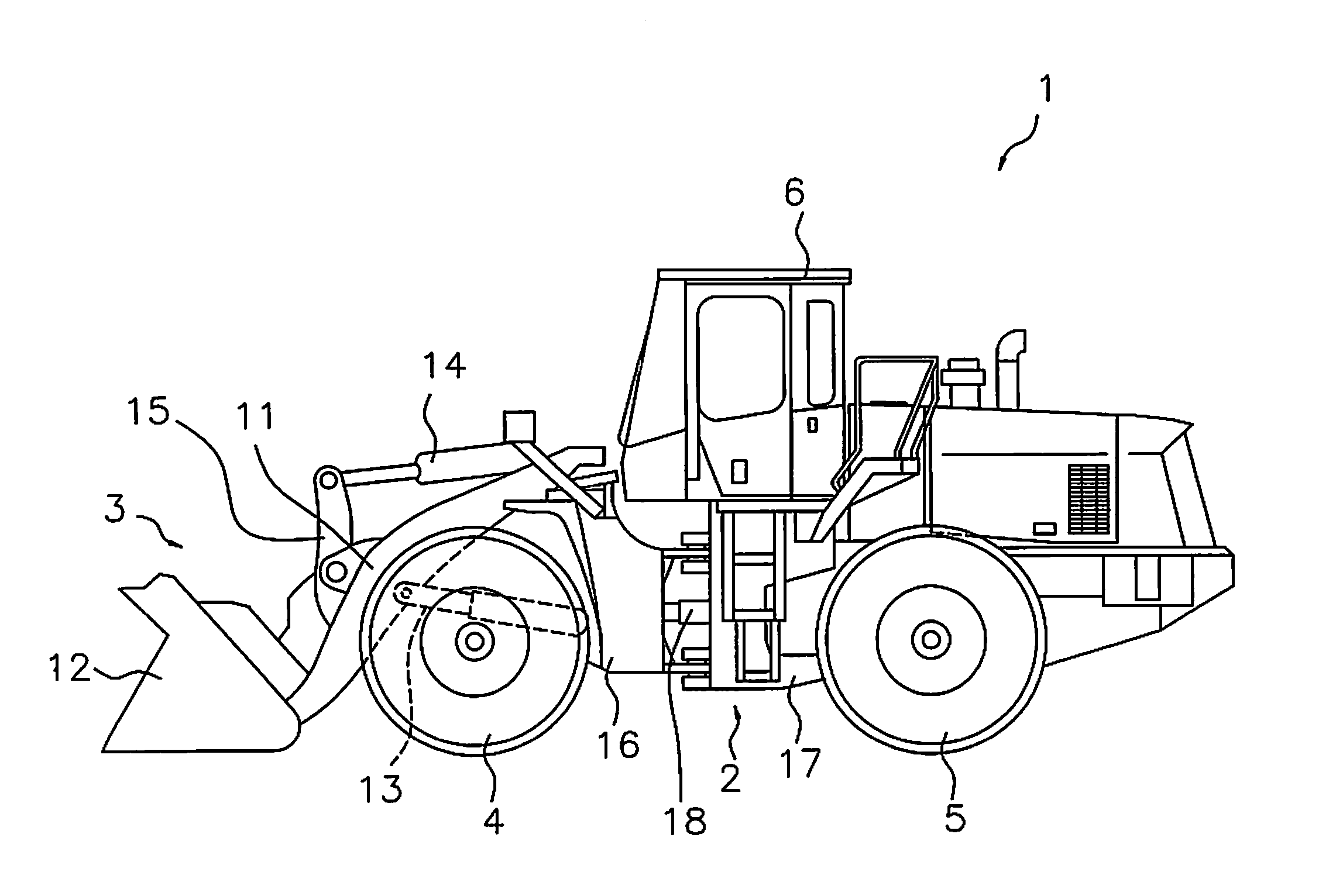
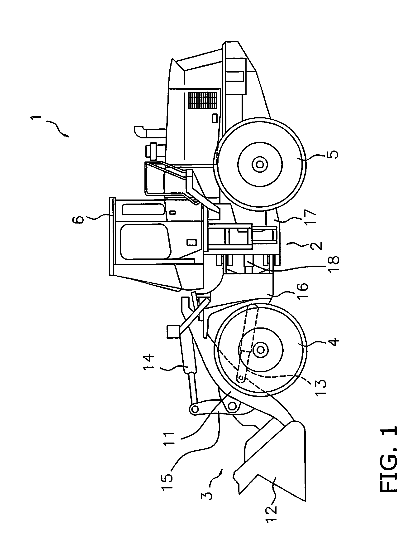
[0031]Exemplary embodiments of the present invention will be explained in detail with reference to the figures. FIG. 1 is a side view of a work vehicle 1 according to an exemplary embodiment of the present invention. As illustrated in FIG. 1, the work vehicle 1 is equipped with a vehicle body frame 2, a work implement 3, traveling wheels 4 and 5, and an operating cabin 6. The work vehicle 1 is a wheel loader and travels due to the traveling wheels 4 and 5 being rotated and driven. The work vehicle 1 is able to carry out work, such as excavation, by using the work implement 3.

[0032]The work implement 3 and the traveling wheels 4 and 5 are attached to the vehicle body frame 2. The work implement 3 is driven by hydraulic fluid from a below mentioned work implement pump 23 (see FIG. 2). The work implement 3 has a boom 11 and a bucket 12. The boom 11 is mounted on the vehicle body frame 2. The work implement 3 includes a lift cylinder 13 and a bucket cylinder 14. The lift cylinder 13 and...


PUM


Abstract

A control unit of a work vehicle has a transmission requirement determination unit, a command-torque determination unit, and a tractive force limiting unit. The transmission requirement determination unit determines a required tractive force on the basis of an operating amount of an accelerator operating member. The required tractive force is a target tractive force of a travel device. The command-torque determination unit determines an output torque of the electric motor so that the tractive force of the vehicle reaches the required tractive force. The tractive force limiting unit reduces the required tractive force to a value less than a value corresponding to the operating amount of the accelerator operating member when the vehicle is excavating.

Description

CROSS-REFERENCE TO RELATED APPLICATIONS[0001]This application is a U.S. National stage application of International Application No. PCT / JP2014 / 082556, filed on Dec. 9, 2014. This U.S. National stage application claims priority under 35 U.S.C. §119(a) to Japanese Patent Application No. 2014-014215, filed in Japan on Jan. 29, 2014, the entire contents of which are hereby incorporated herein by reference.BACKGROUNDField of the Invention[0002]The present invention relates to a work vehicle and a control method for the work vehicle.[0003]Background Information A work vehicle may travel and perform work using a work implement at the same time. In this case, it is important to maintain a balance between a tractive force of the vehicle and a driving power for the work implement. For example, work may be carried out that involves traveling forward and loading a bucket while excavating dirt and driving the lift arm to raise the bucket. In this type of work, tractive force acts on the lifting ...

Claims


Application Information

Patent Timeline
Patent Type & Authority Applications(United States)
IPC IPC(8): E02F3/42E02F9/20E02F9/22E02F3/34
CPCE02F3/422E02F3/34Y10S903/902E02F9/2253E02F9/2079E02F9/2075B60K6/445B60W10/08B60W20/00E02F9/2292E02F9/2296B60K6/387B60W2300/17B60W2540/10B60W20/10Y02T10/62B60K6/54
Inventor YOSHIZAWA, MASAOMIYAMOTO, SHUNSUKEKISHIMOTO, YASUKI
Owner KOMATSU LTD
Why Eureka
Try Eureka