
Method and equipment for identifying and measuring alternating current interference in buried ducts

a technology of alternating current interference and buried ducts, which is applied in the direction of instruments, gas/liquid distribution and storage, material analysis, etc., can solve the problems of carbon steel corrosion and the inability to form a protective passive layer

Inactive Publication Date: 2015-12-17
INST DE PESQUISAS TECHCAS DO ESTADO DE SAO PAULO
View PDF0 Cites 10 Cited by
  • Summary
  • Abstract
  • Description
  • Claims
  • Application Information

AI Technical Summary

Benefits of technology

The patent text is trying to prevent soil from getting contaminated with copper ions, which can cause coating to be put on the surface of the corrosion. The technical effect of this is to prevent the coating from getting damaged and to ensure accurate measurement of the corrosion process.

Problems solved by technology

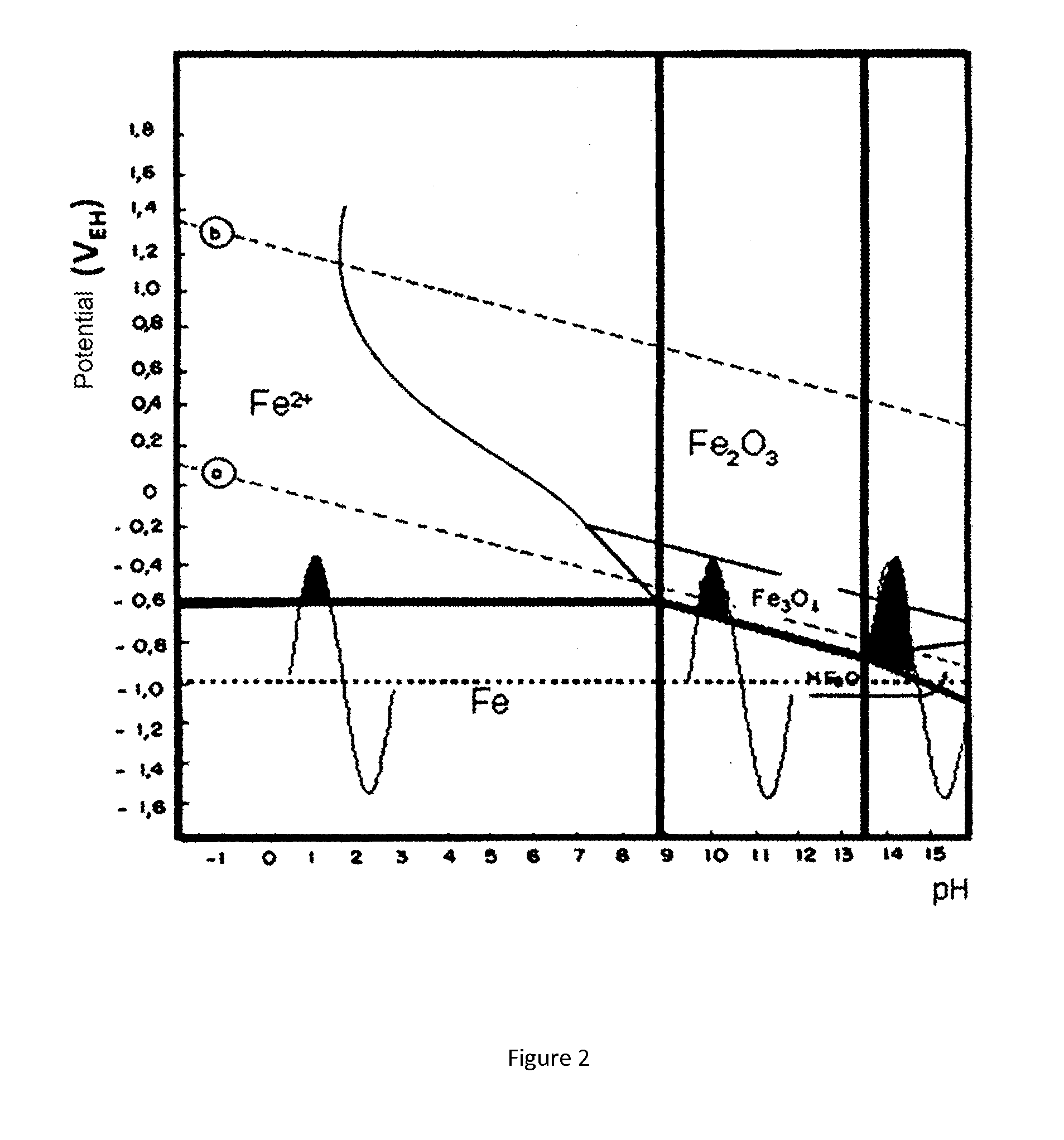
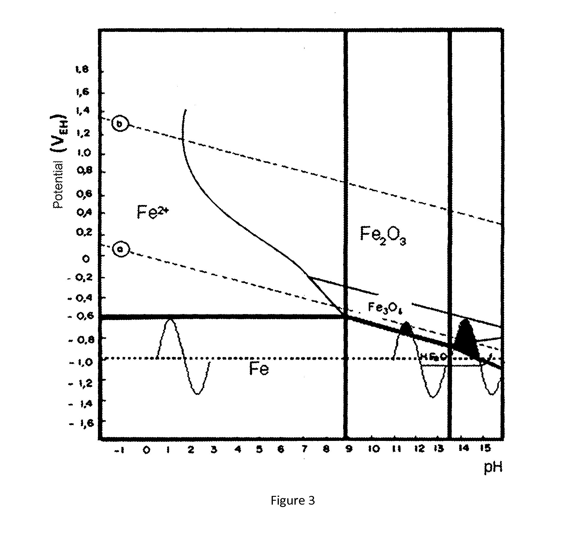
Accordingly, the corrosion of carbon steel occurs because of the irreversibility of the reaction of iron corrosion in cases of limited alkalinization, and the impossibility of formation of a protective passive layer due to the fluctuation between the state of corrosion and passivity, in cases markedly alkalinization.

Method used


Image

  • Method and equipment for identifying and measuring alternating current interference in buried ducts
  • Method and equipment for identifying and measuring alternating current interference in buried ducts
  • Method and equipment for identifying and measuring alternating current interference in buried ducts

Examples


Embodiment Construction

[0044]As stated previously, we developed a probe consisting of a reference electrode of copper / copper sulfate (ECSC) and permanent corrosion coupons, preferably four, and this probe was coupled to the electronic switching device, also developed in the context of this invention.

[0045]In the market, there are marketed probes constructed with reference electrodes and a corrosion coupon are called permanent reference electrodes. The corrosion coupon of these probes is electrically connected to the duct in test points (PTE), and it was used to estimate corrosion rates, and the reference electrode to monitor the pipe / soil potential for cathodic protection. In general, these probes remain buried for long periods, and in practice measure errors occur as time passes. Studies have shown that these errors are due to the passivation of the corrosion coupon due to the diffusion of copper ions crossing the porous plate of the reference electrode and are directed to the corrosion coupon. These ion...


PUM


Abstract

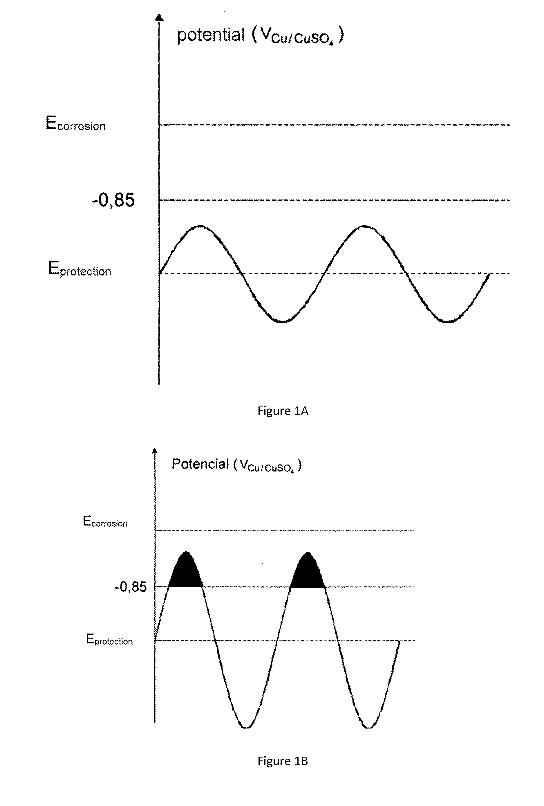
This invention, which pertains to the field of testing of the corrosion-resistance of materials, includes devices (a probe formed by a permanent reference electrode with corrosion coupons and an electronic switch) and a measurement method for evaluating the probability of corrosion of buried ducts due to alternating current (AC), and aims at providing a methodology that eliminates ohmic losses and allows the desired measurement to be obtained. For that purpose, a probe formed by a permanent copper or copper sulphate reference electrode (ECSC) with four corrosion coupons was developed, and an electronic switch which was also developed within the scope of this invention is coupled to this probe. This assembly (probe and switch), associated with a preferably portable digital oscilloscope or a data acquisition device with digital signal processing (DSP), makes it possible to obtain the waveform of the pipe / ground potential AC+DC off, and hence the peak potential of this waveform, this value being used to predict the corrosion of buried, cathode-protected ducts due to alternating current, on the basis of the criterion that corrosion due to alternating current will not occur or will be insignificant if the peak of the waveform of the pipe / ground potential AC+DC off is more negative than −0.85 VECSC. The present invention can also be directly used for monitoring external corrosion of ground ducts and to verify the real cathode protection potential of these ducts. In order to ensure the integrity of the ducts, this equipment can be installed at test points, at valve boxes and cathode protection rectifiers, as well as in zones where corrosion is suspected.

Description

[0001]The present invention relates to the research sector of the resistance of materials to corrosion, presents devices (probe consists of a permanent reference electrode with corrosion coupons and an electronic switcher) and measurement procedure to assess the probability of corrosion occur by alternating current (AC) of buried ducts, aiming to establish a methodology that eliminates the ohmic drop and thus allows achieving the desired measure.[0002]For this purpose, it was developed a probe consisting of a permanent reference electrode of copper / copper sulfate (ECSC) and four corrosion coupons, and this probe was coupled to an electronic switching device, also developed in the scope of this invention. This set (probe+switching device) associated with a digital oscilloscope or a data acquisition device with digital signal processing (DSP—digital signal processing), preferably portable, allows obtaining the waveform of potential pipe / soil AC+DC off and the consequent obtainment of ...

Claims


Application Information

Patent Timeline
IPC IPC(8): G01N17/00G01N17/04
CPCG01N17/043G01N17/006F17D5/08
Inventor PANOSSIAN, ZEHBOURABUD FILHO, SERGIO EDUARDOALMEIDA, NEUSVALDO LIRA DEPEREIRA FILHO, MARIO LEITESILVA, DIOGO DE LIMA E
Owner INST DE PESQUISAS TECHCAS DO ESTADO DE SAO PAULO
Learn More