Direct lift process apparatus

a technology of process apparatus and substrate, which is applied in the direction of pile separation, transportation and packaging, manufacturing tools, etc., can solve the problem that the photomask is sensitive to defects

Active Publication Date: 2015-12-17
APPLIED MATERIALS INC
View PDF10 Cites 208 Cited by
  • Summary
  • Abstract
  • Description
  • Claims
  • Application Information

AI Technical Summary

Benefits of technology

[0010]One embodiment provides a substrate support assembly. The substrate support assembly includes a substrate pedestal having an upper surface for receiving and supporting a substrate, a cover plate disposed on the substrate support pedestal, and two or more lift pins movably disposed through the substrate support pedestal and the cover plate. The cover includes disk body having a central opening. The central opening surrounds the upper surface of the substrate pedestal. Each of the two or more lift pins comprises one or more contact pads, and the contact pads of the lift pins extend into to the central opening of the cover plate to receive and support a substrate at an edge region of the substrate.
[0011]Another embodiment provides a process chamber. The process chamber includes a chamber body enclosing a chamber volume, a plasma source positioned to generate a plasma in the chamber volume, and a substrate support assembly disposed in the chamber volume. The substrate support assembly includes a substrate pedestal having an upper surface for receiving and supporting a substrate in the chamber volume, a cover plate disposed on the substrate support pedestal, wherein the cover plate includes a disk body having a central opening, and the central opening surrounds the upper surface of the substrate pedestal, and two or more lift pins movably disposed through the substrate support pedestal and the cover plate, wherein each of the two or more lift pins comprises one or more contact pads, and the contact pads of the lift pins extend into to the central opening of the cover plate to receive and support a substrate at an edge region of the substrate.
[0012]Another embodiment provides a method for supporting and transferring a substrate. The method includes raising two or more lift pins above a cover plate disposed around a substrate pedestal having an upper surface for receiving and supporting a substrate, wherein the cover plate has a central opening surrounding the upper surface, and each of the two or more lift pins has one or more contact pads extending into the central opening of the cover plate, receiving a substrate with the two or more lift pins by supporting the substrate at an edge region with the contact pads on the two or more lift pins, and lowering the two or more lift pins into lift pin recesses formed in the cover plate to transfer the substrate onto the upper surface of the substrate pedestal.

Problems solved by technology

Photomasks are sensitive to defects, such as scratches, and particles, because defects and particles may alter the light transmission properties of the photomasks.

Method used


Image

  • Direct lift process apparatus
  • Direct lift process apparatus
  • Direct lift process apparatus

Examples


Embodiment Construction

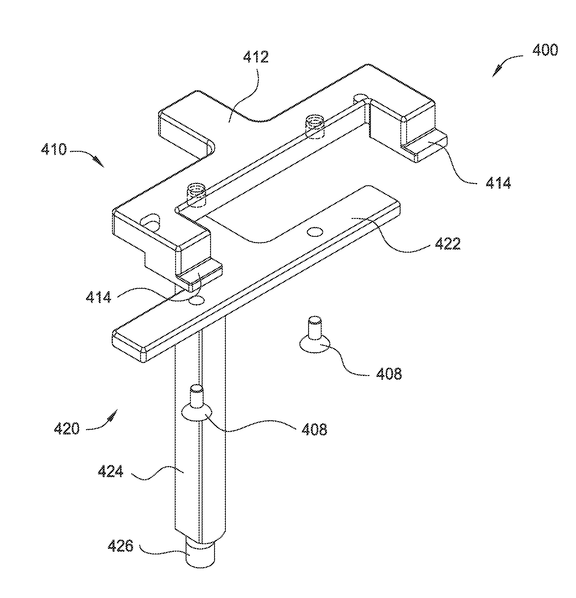
[0022]The present disclosure generally relates apparatus and methods for handling photomasks, reticles or other substrates during fabrication. It should be noted that the terms “mask”, “photomask” and “reticles” may be used interchangeably to denote generally a substrate containing a pattern.

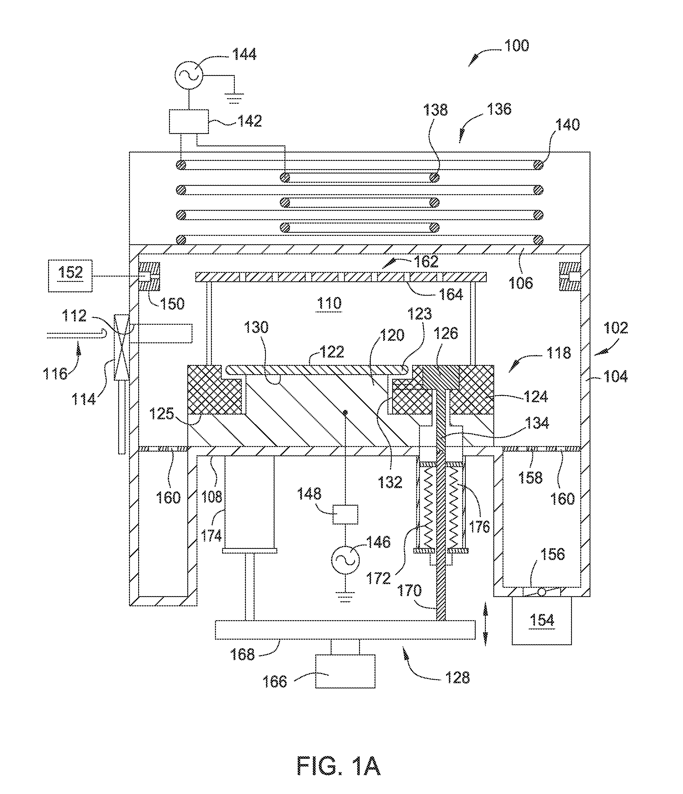
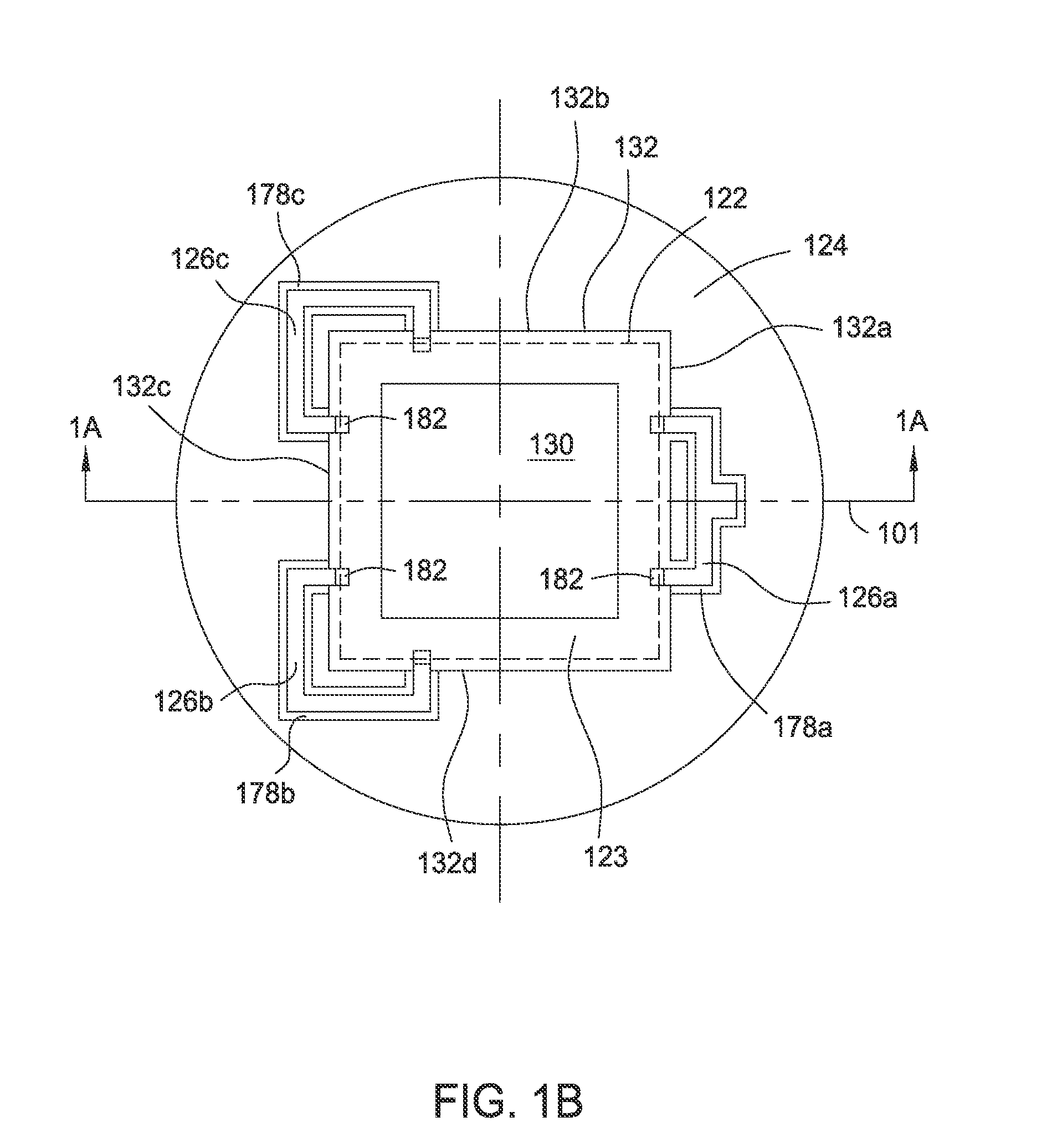
[0023]More particularly, the present disclosure relates to lift pins with reduced contact areas and a cover plate used in a plasma process chamber. The lift pins according to the present disclosure may include a mounting pole that is self supportive without requiring external supporting structure. The self supportive lift pins provide smooth and balanced movement and eliminate friction with additional supporting structure, thus reducing particle generation. The lift pins may include one or more contact pads for contacting substrates with reduced contact areas, thus reducing particle generation and lowering the possibility of scratching the substrate being handled. The cover plate of the present ...


PUM

PropertyMeasurementUnit
frequencyaaaaaaaaaa
circular shapeaaaaaaaaaa
plasma resistantaaaaaaaaaa

Abstract

The present disclosure provides a substrate support assembly includes a substrate pedestal having an upper surface for receiving and supporting a substrate, a cover plate disposed on the substrate support pedestal, and two or more lift pins movably disposed through the substrate support pedestal and the cover plate. The cover plate includes a disk body having a central opening. The two or more lift pins are self supportive. Each of the two or more lift pins comprises one or more contact pads, and the contact pads of the lift pins extend into to the central opening of the cover plate to receive and support a substrate at an edge region of the substrate.

Description

CROSS-REFERENCE TO RELATED APPLICATIONS[0001]This application claims priority to U.S. Provisional Patent Application Ser. No. 62 / 012,159, filed on Jun. 13, 2014, which herein is incorporated by reference.BACKGROUND[0002]1. Field[0003]Embodiments of the present disclosure relate to apparatus and methods for supporting and transferring substrates during photomask fabrication.[0004]2. Description of the Related Art[0005]Photomasks used in the patterning a substrate typically include a glass or quartz substrate having a patterned metal-containing layer. The patterned metal-containing layer is typically generated by etching with a radiation beam, such as a electron[0006]Photolithographic photomasks typically comprise a substrate of an optically transparent silicon based material, such as quartz. A light-shielding layer of metal, typically chromium, is patterned on the surface of the substrate. The metal layer is patterned and etched to form features which define the pattern, and correspo...

Claims


Application Information

Patent Timeline
Patent Type & Authority Applications(United States)
IPC IPC(8): H01L21/67H01L21/677H01L21/687
CPCH01L21/67069H01L21/67742H01L21/68742C23C16/458H01J37/32715H01J37/32788
Inventor NGUYEN, KHIEMSINGH, SARAVJEETSABHARWAL, AMITABH
Owner APPLIED MATERIALS INC
Why Eureka
Try Eureka