Power transmission device and power receiving device
- Summary
- Abstract
- Description
- Claims
- Application Information
AI Technical Summary
Benefits of technology
Problems solved by technology
Method used
Image

Examples
first embodiment
Power Transmission System 1000
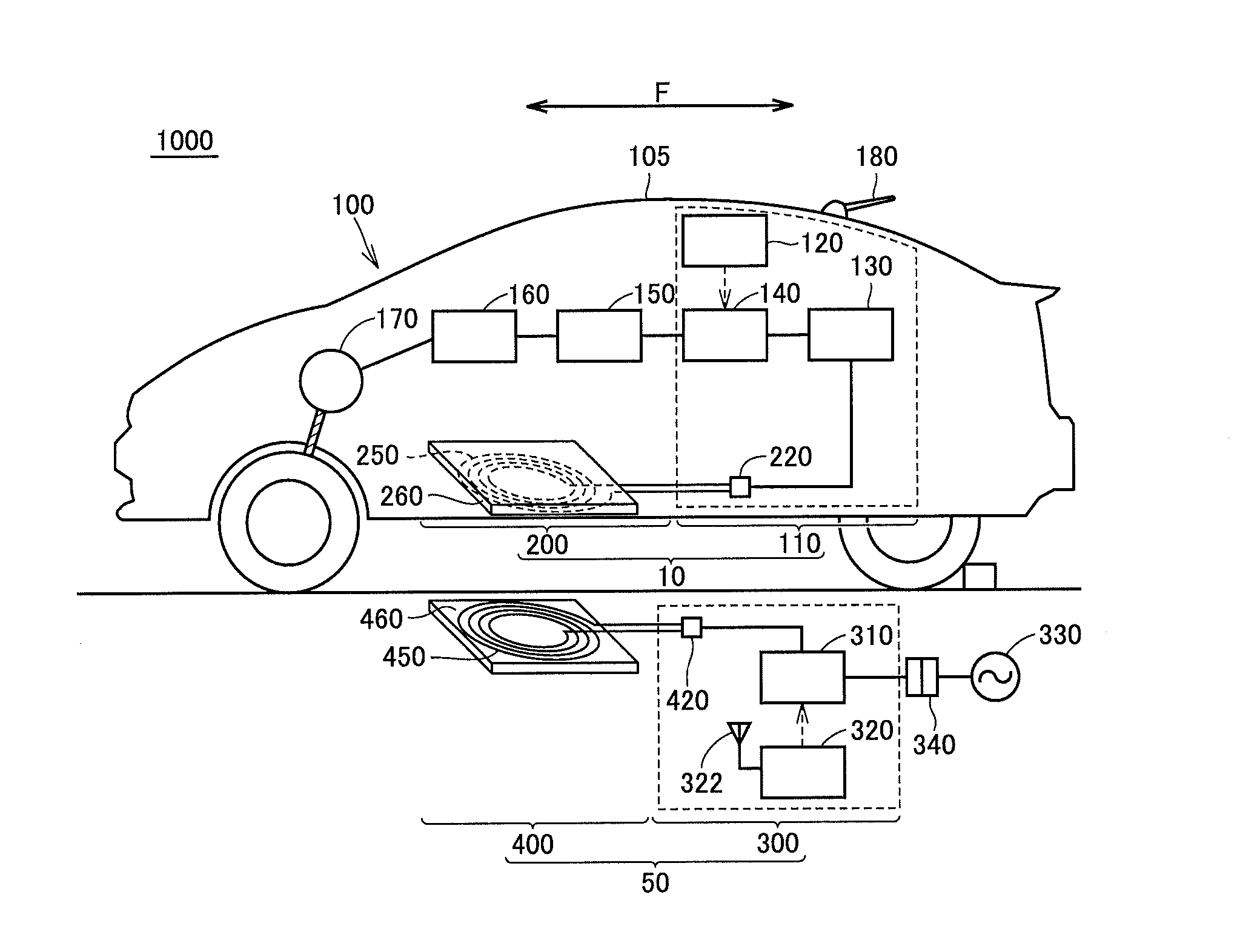
[0033]With reference to FIG. 1, a power transmission system 1000 for transmitting power in a noncontact manner will be described. Power transmission system 1000 includes a power receiving device 10 mounted on an electric vehicle 100, and a power transmission device 50 installed on a facility side such as a parking area. Electric vehicle 100 includes power receiving device 10 and a vehicle body 105.
[0034](Power Receiving Device 10)
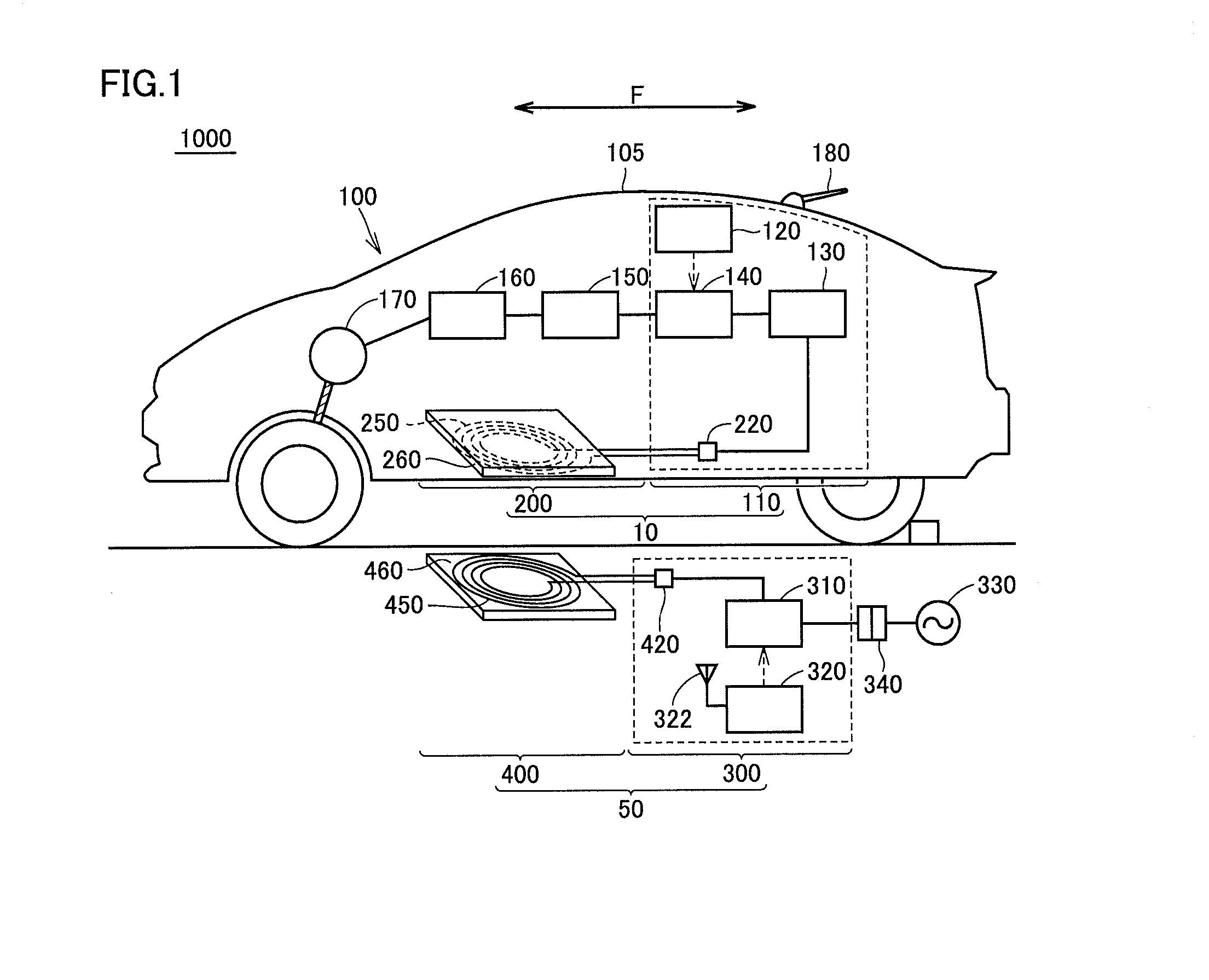
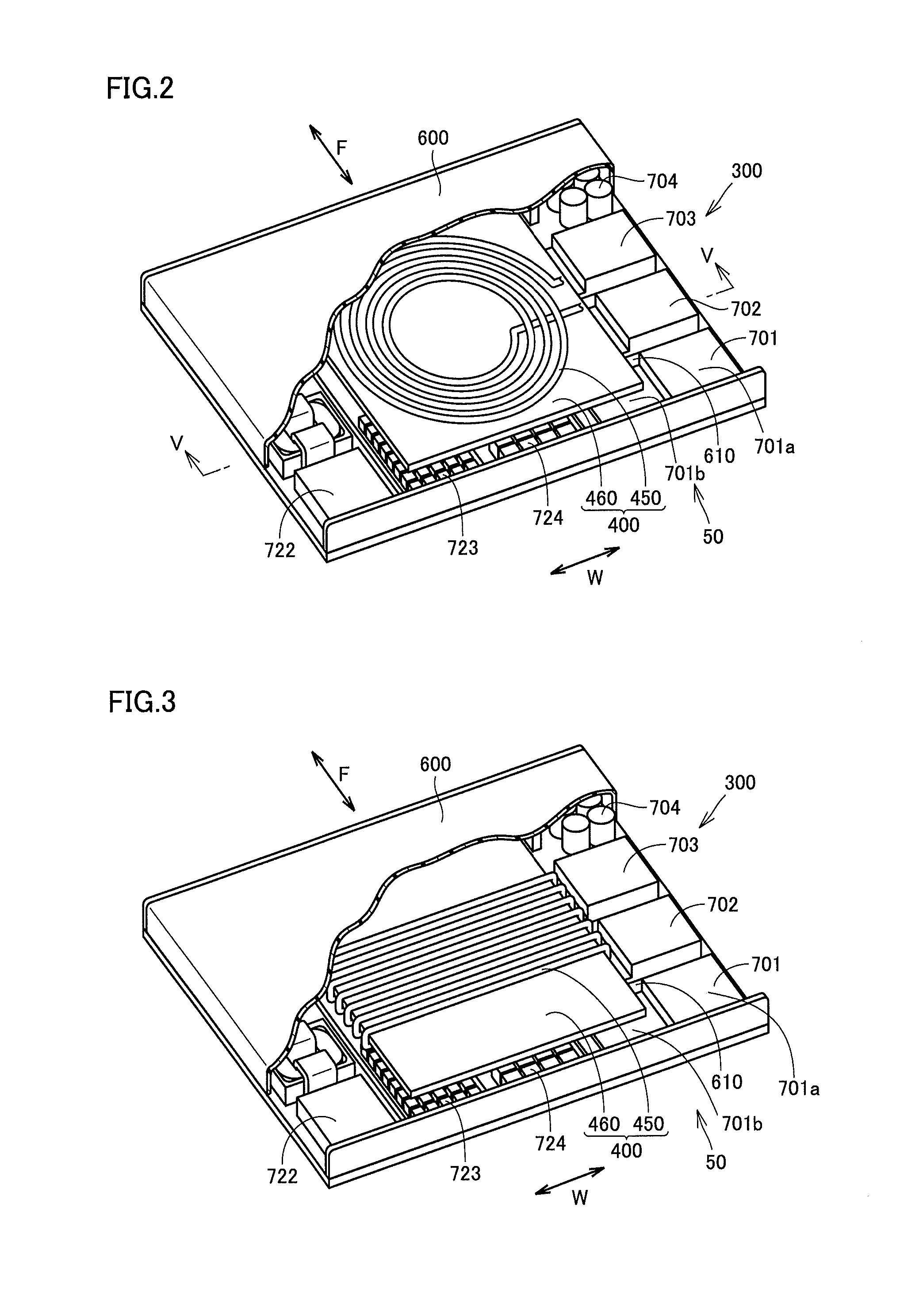
[0035]Power receiving device 10 includes a power receiving unit 200, and an apparatus unit 110 provided between power receiving unit 200 and a battery 150 serving a storage device for storing power received by power receiving unit 200. Power receiving unit 200 has a power receiving coil 250 and a plate shaped ferrite core 260. As described later, as power receiving coil 250, any of a spiral type coil (see FIG. 2) and a wound type coil (see FIG. 3) may be employed. FIG. 1 shows spiral type power receiving coil 250. Apparatus uni...
second embodiment
[0066]With reference to FIGS. 10 to 12, a power transmission device 50A according to this embodiment will be now described. FIG. 10 is a plan view of power transmission device 50A in this embodiment, FIG. 11 is a sectional view taken along a line XI-XI in FIG. 10, and FIG. 12 is an enlarged partially sectional view of another mode of power transmission device 50A in this embodiment.
[0067]An internal mechanism of power transmission device 50A according to this embodiment is the same as that of the above first embodiment, and is different in a configuration of a housing 600A employed in this embodiment. A heating value of the first devices disposed around a power transmission unit 400 is sometimes larger than a heating value of the second devices disposed between power transmission unit 400 and a bottom plate 610. For example, a heating value of a high part 701a of a switching power supply 701 configuring an AC / DC unit, and a heat sink 713, filter inductors 716, 717, 720, and the like...
third embodiment
[0080]With reference to FIGS. 13 and 14, a configuration of a power receiving device 10 will be described as a third embodiment. FIG. 13 is a perspective view showing a configuration of a power receiving device 10 employing a spiral type power receiving coil 250, and FIG. 14 is a perspective view showing a configuration of a power receiving device 10 employing a wound type power receiving coil 250. Power receiving device 10 in each of FIGS. 13 and 14 is illustration of a state where a facility side in a case where power receiving device 10 is mounted in a vehicle is an upper side (illustration of a state turned upside down). Accordingly, the top in the drawing is a lower side (ground side) in the following description.
[0081]Power receiving device 10 basically has a configuration similar to the configurations of the above power transmission devices 50 and 50A, and has a power receiving unit 200 for receiving power from power transmission device 50 in a noncontact manner, an apparatus...
PUM
 Abstract
Description
Claims
Application Information
 - R&D
- Intellectual Property
- Life Sciences
- Materials
- Tech Scout
- Unparalleled Data Quality
- Higher Quality Content
- 60% Fewer Hallucinations
Browse by: Latest US Patents, China's latest patents, Technical Efficacy Thesaurus, Application Domain, Technology Topic, Popular Technical Reports.
© 2025 PatSnap. All rights reserved.Legal|Privacy policy|Modern Slavery Act Transparency Statement|Sitemap|About US| Contact US: help@patsnap.com