Motor control system and interface
a technology of motor control and interface, applied in the direction of motor/generator/converter stopper, dynamo-electric converter control, instruments, etc., can solve the problems of affecting the speed range and efficiency of the motor with this three-wire schem
- Summary
- Abstract
- Description
- Claims
- Application Information
AI Technical Summary
Benefits of technology
Problems solved by technology
Method used
Image

Examples
Embodiment Construction
[0014]Before describing the present invention, some introductory concepts and terminology are explained. As used herein, the terms “voltage level” and “signal level” mean the voltage magnitude of the respective DC signal. The terms “discontinuous signal” and “discontinuous analog signal” both mean an analog signal generally having a non-zero voltage level wherein the signal voltage level may drop to zero in a near instant and subsequently jump back to the non-zero voltage level. The term “desired speed” means the speed at which a motor controller instructs a motor driver to operate motor. The term “average pulse width” means the average pulse width within a pulse width modulated signal taken over a constant time period.
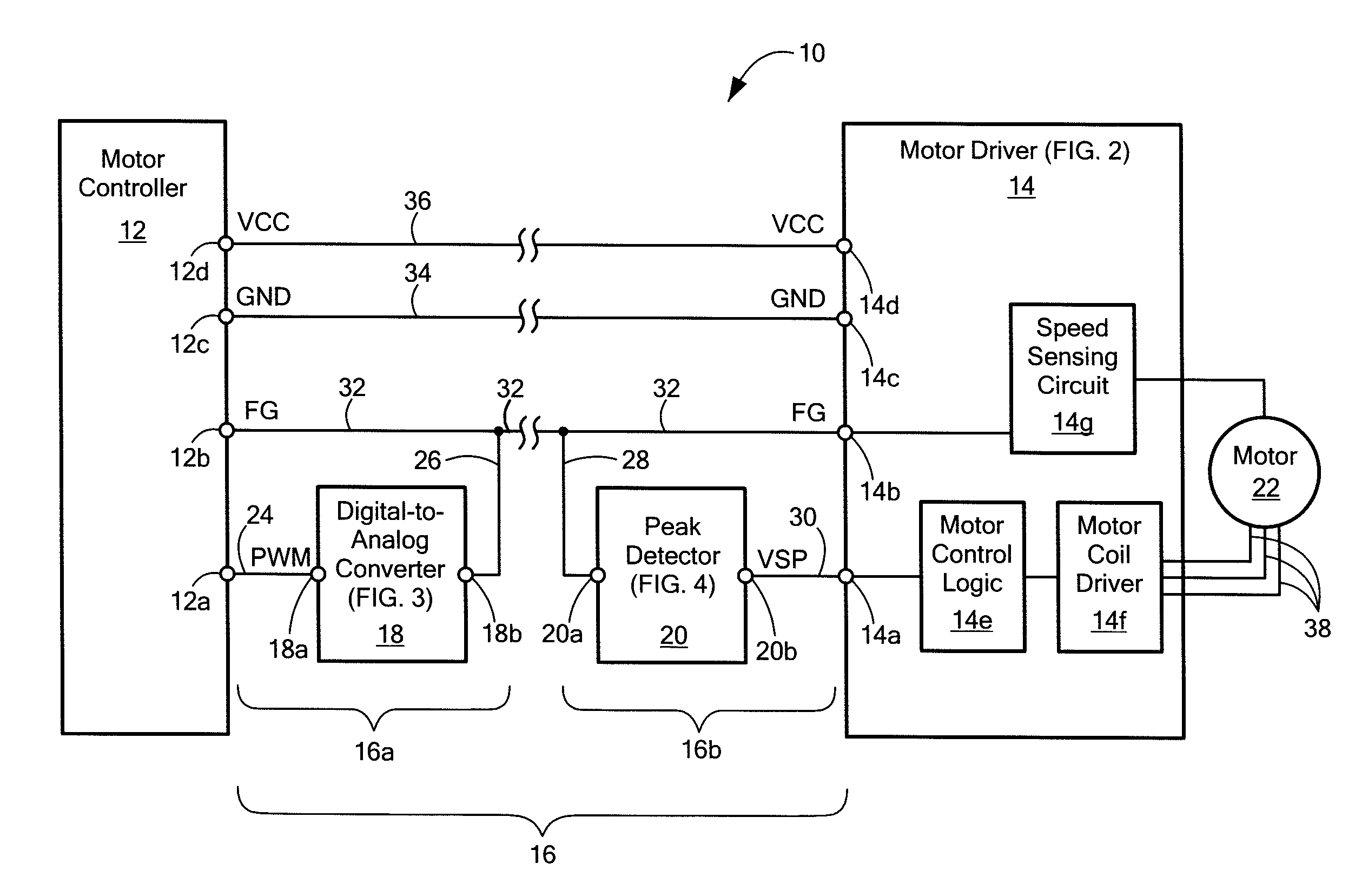
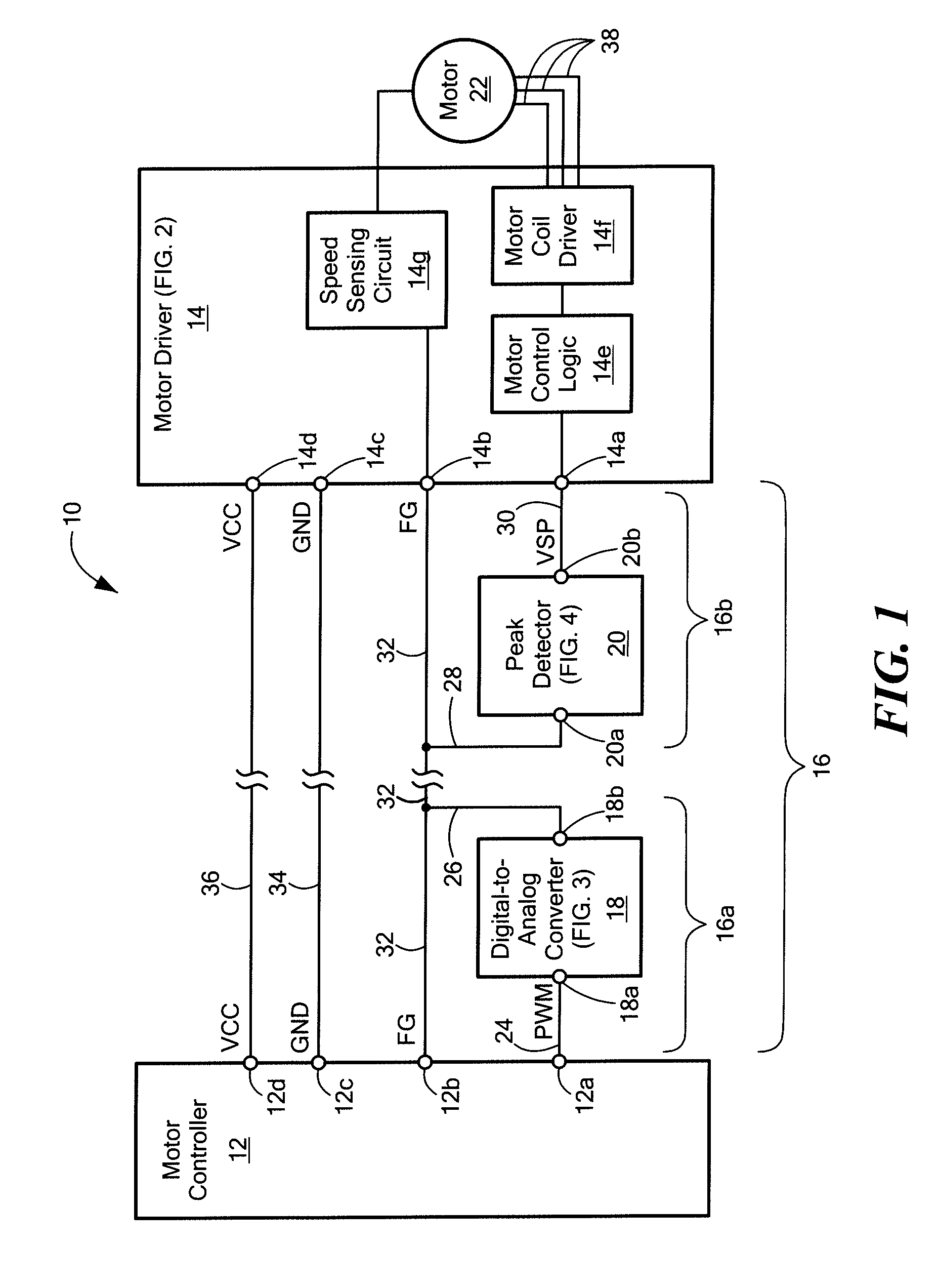
[0015]FIG. 1 shows a motor control system 10 for controlling a motor 22. The control system 10 includes a motor controller 12, a motor driver 14, and an interface 16. The motor controller 12 includes a motor speed control output terminal 12a, motor speed feedback inpu...
PUM
 Abstract
Description
Claims
Application Information
 - R&D
- Intellectual Property
- Life Sciences
- Materials
- Tech Scout
- Unparalleled Data Quality
- Higher Quality Content
- 60% Fewer Hallucinations
Browse by: Latest US Patents, China's latest patents, Technical Efficacy Thesaurus, Application Domain, Technology Topic, Popular Technical Reports.
© 2025 PatSnap. All rights reserved.Legal|Privacy policy|Modern Slavery Act Transparency Statement|Sitemap|About US| Contact US: help@patsnap.com