This helps you quickly interpret patents by identifying the three key elements:
Problems solved by technology
Method used
Benefits of technology
Benefits of technology
This patent is about a brush cutter with battery packs. The battery packs are arranged in a way that the cutter's center of gravity is positioned in the middle of the cutter, which prevents it from tilting to the sides when it is placed on a horizontal support. The battery packs are also spaced from the ground to prevent damage if they come into contact with it. Additionally, the battery packs are arranged in parallel to make it easier for users to attach or remove them.
Image
Click on the blue label to locate the original text in one second.
Reading with bidirectional positioning of images and text.
Examples
modification 1
[0056]
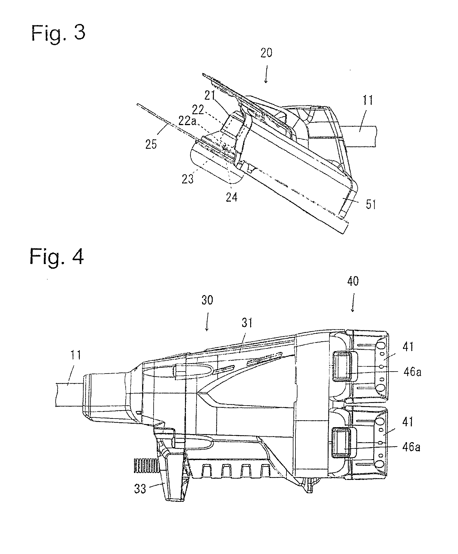
[0057]In a modification 1 of the brush cutter shown in FIG. 10, the attachment 32 within the rear end housing 31 is provided with a container 34 enclosing the periphery of battery packs 41, 41 to prevent adherence of contaminants thereto. The battery pack container 34 is formed at its one side wall with an insert opening 34a for the battery packs 41. When the battery packs 41, 41 each are inserted into the container 34 through the opening 34a and shifted inward along the guide rails 32b, 32b, the hook 46 is engaged with the latch portion 32c of attachment 32 to retain the battery packs 41 in place.
[0058]The attachment 32 is provided with a resilient member 35 biasing outward the battery packs 41 inserted in the container 34. When it is desired to take out the battery packs, the release button 46a is pushed to disengage the hook 46 from the latch portion 32c. Thus, as shown in FIG. 10, the battery packs 41, 41 are moved outward through the insert opening 34a under the biasing f...
modification 2
[0059]
[0060]As shown in FIG. 11, the battery packs 41, 41 may be arranged vertically in parallel on the back portion of rear end housing 31. In this modification, the two attachments 32, 32 are provided laterally in parallel on the back portion of rear end housing 31, and the pair of guide rails 32b, 32b is provided vertically at the both sides of each connector 32a of attachments 32, 32. Thus, the battery packs 41, 41 are mounted in place by downward slide movement along the guide rails 32b, 32b
[0061]With such arrangement of the battery packs, each center of gravity G1 is positioned at left and right sides of the vertical centerline Cw to ensure balance of the brush cutter in a left-and-right direction. In this modification 2, the battery pack container 34 and resilient member 35 may be provided as in the modification 1.
modification 3
[0062]
[0063]As shown in FIG. 12, the battery packs 41, 41 arranged as in the modification 1 may be inclined backward at their upper sides. In this modification, the attachment portions 32 and guide rails 32b, 32b are inclined backward at their upper sides.
[0064]With such arrangement of the battery packs, the battery packs 41, 41 can be mounted in place by downward pushing and removed by bringing upward. In this modification 3, the battery pack container 34 and resilient member 35 may be provided as in the modification 1.
PUM
Abstract
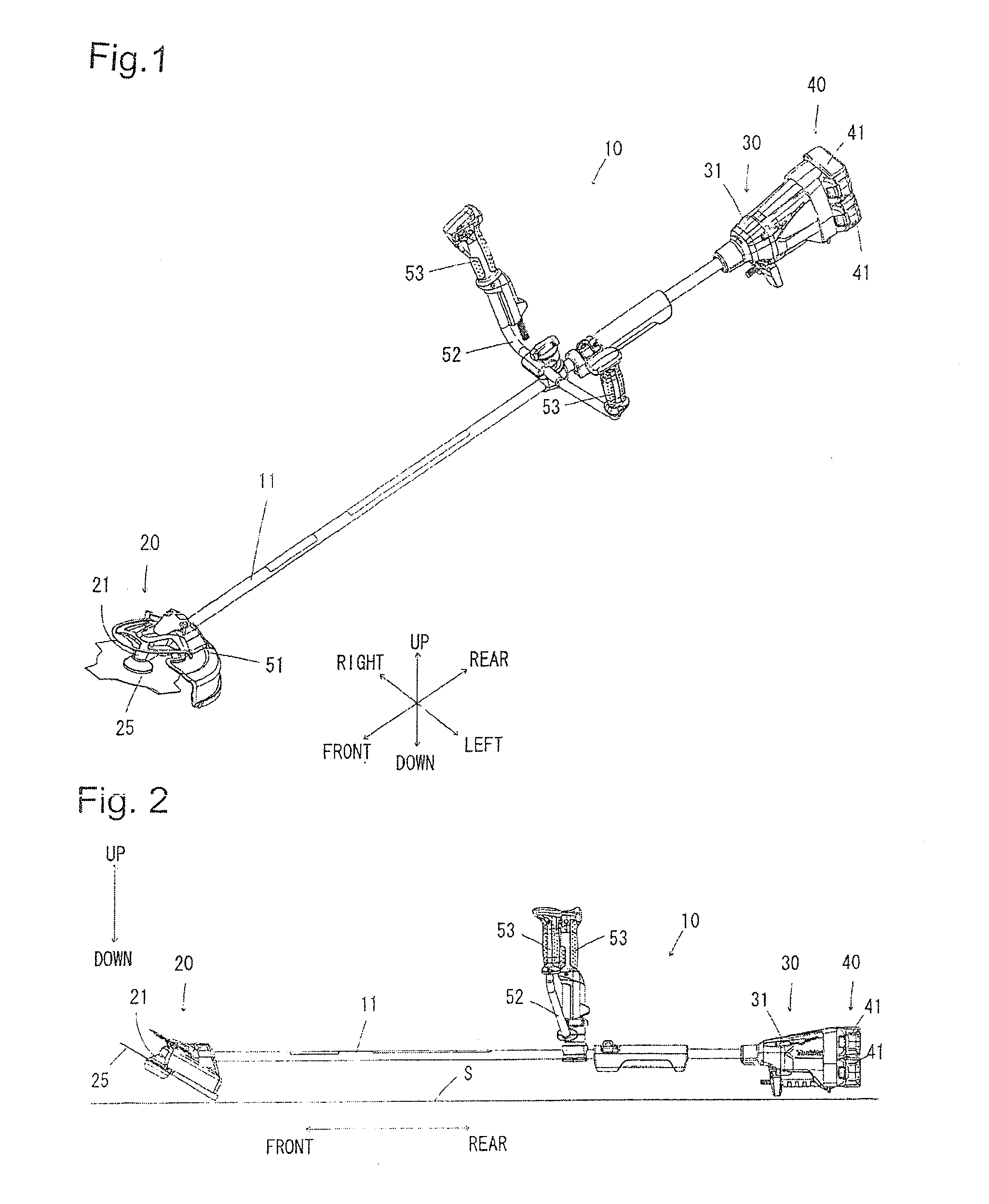
A brush cutter includes a frame rod, a front end housing fixedly mounted to a front end of the frame rod, a cutting blade mounted on a support shaft within the front end housing, a rear end housing fixedly mounted to a rear end of the frame rod, an electric motor mounted within the rear end housing for rotation of the cutting blade, and a source of power supply for supplying electric power to the motor. In the brush cutter, a plurality of rechargeable battery packs adapted to use in electric power tools are used as the source of power supply for the motor.
Description
TECHNICAL FIELD[0001]The present invention relates to a brush cutter for cutting brush, lawn and the like.TECHNICAL BACKGROUND[0002]Disclosed in Japanese Patent Laid-open Publication 1 (2011-142859) is a brush cutter comprising a frame rod, a cutter head provided within a front end of the frame rod and a controller head provided in a rear end of the frame rod. The cutter head of the brush cutter includes a front housing fixed to the front end of the frame rod, an electric motor mounted within the front housing, a rotary shaft supported within the front housing to be driven by the electric motor, and a cutting blade mounted to the rotary shaft. The controller head includes a rear housing fixed to the rear end of the frame rod and a controller contained in the rear housing. In the brush cutter, a battery pack is detachably mounted within the rear housing.[0003]In the brush cutter, a single battery pack contained within the rear housing is in general in the form of a large size battery...
Claims
Application Information
Patent Timeline
Application Date:The date an application was filed.
Publication Date:The date a patent or application was officially published.
First Publication Date:The earliest publication date of a patent with the same application number.
Issue Date:Publication date of the patent grant document.
PCT Entry Date:The Entry date of PCT National Phase.
Estimated Expiry Date:The statutory expiry date of a patent right according to the Patent Law, and it is the longest term of protection that the patent right can achieve without the termination of the patent right due to other reasons(Term extension factor has been taken into account ).
Invalid Date:Actual expiry date is based on effective date or publication date of legal transaction data of invalid patent.

