Outboard propulsion system for vessels

a propulsion system and outboard technology, applied in the direction of marine propulsion, vessel construction, propulsive elements, etc., can solve problems such as unbalanced dynamical balance, and achieve the effects of reducing the number of cylinders

Active Publication Date: 2015-12-24
INTERACTIVE FULLY ELECTRICAL VEHICLES SRL
View PDF4 Cites 6 Cited by
  • Summary
  • Abstract
  • Description
  • Claims
  • Application Information

AI Technical Summary

Benefits of technology

[0003]The object of the invention is that of providing a system of this type which is characterized by high efficiency, lightness and reduced dimensions.SUMMARY OF THE INVENTION
[0011]In one variant, the toroid electric motor is provided with windings and permanent magnets arranged only along a portion, such as 70%, of the entire circumferential extension of the toroid motor, so that at the remaining portion of the circumferential extension of the motor, the stator and the rotor can be made with a reduced dimension in the direction parallel to the motor axis, to advantage of a lower hydrodynamic drag.
[0014]According to a further embodiment, which however does not form part of the annexed claims, a propulsion unit of the above indicated type can be used also for aerial propulsion in small unmanned aircrafts of the Vertical Take-off and Landing (VTOL) type, which can be used for example as drones equipped with a camera or a video camera for surveillance activities or for conveying small payloads. A vehicle of this type can be equipped for example with three or more propulsion units with vertical axes arranged around a central supporting structure, which for example can house an onboard electronic unit and transmitting / receiving means for communication with a control station. The configuration of each propulsion unit is identical to that described above for the outboard propeller device, with the difference that in this case the optimal configuration of the blades of the propellers is that which causes the air flow through each rotor to converge into a focusing area arranged at a distance which is 2.8-3.2 times the inner diameter of the rotor. Due to this feature, an aerial propulsion unit according to this embodiment has a greater efficiency and provides a greater lift with respect to the conventional solutions in the field of aerial propulsion for VTOL aircrafts. The known solutions of VTOL aircrafts with three, four or more rotors, both in the version with free rotors and in the version with ducted rotors, are penalized by an excessive aerodynamic drag due to the edge effects on the conventional blades and on the body of the motor, which is arranged at the centre of each rotor. For a given surface covered by the rotors, the losses increase with the number of rotors and with decreasing values of the diameters of the rotors. The higher efficiency and the control on the convergence of the flow through the annular rotors proposed according to this embodiment enable a greater fuel range of the aircraft. The annular rotor according to this embodiment is further characterized by a reduction of the aerodynamic noise, which in conventional rotors is caused by the turbulence originated by the edge effects on the conventional blades.

Problems solved by technology

The potential drawback of a propeller with a single blade is that it is dynamically unbalanced, but this drawback has no detrimental consequences in the case of the invention, since the propeller is integrated within a motor with a toroid configuration, whose structure supports the centrifugal forces.

Method used


Image

  • Outboard propulsion system for vessels
  • Outboard propulsion system for vessels
  • Outboard propulsion system for vessels

Examples


Embodiment Construction

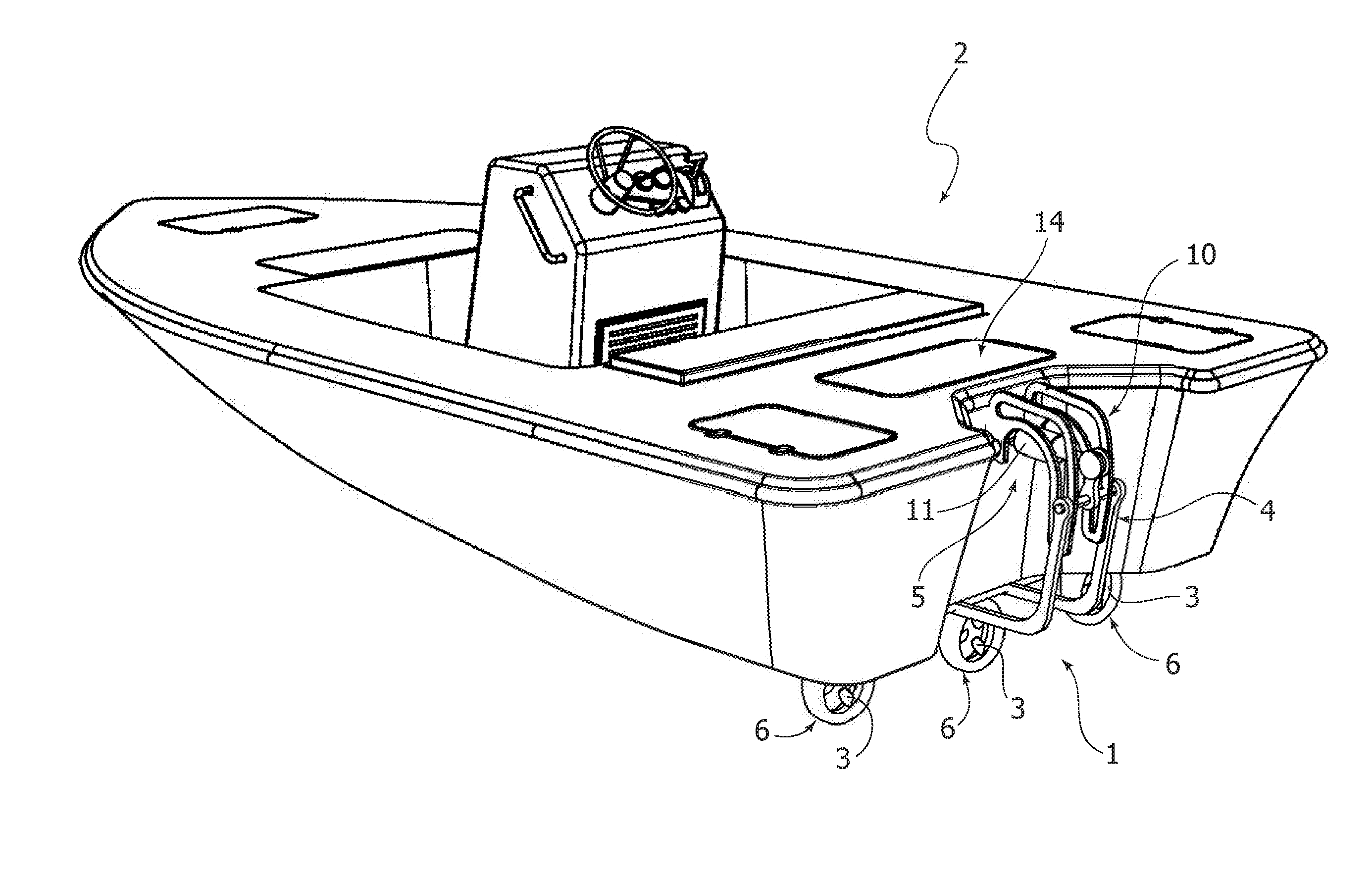
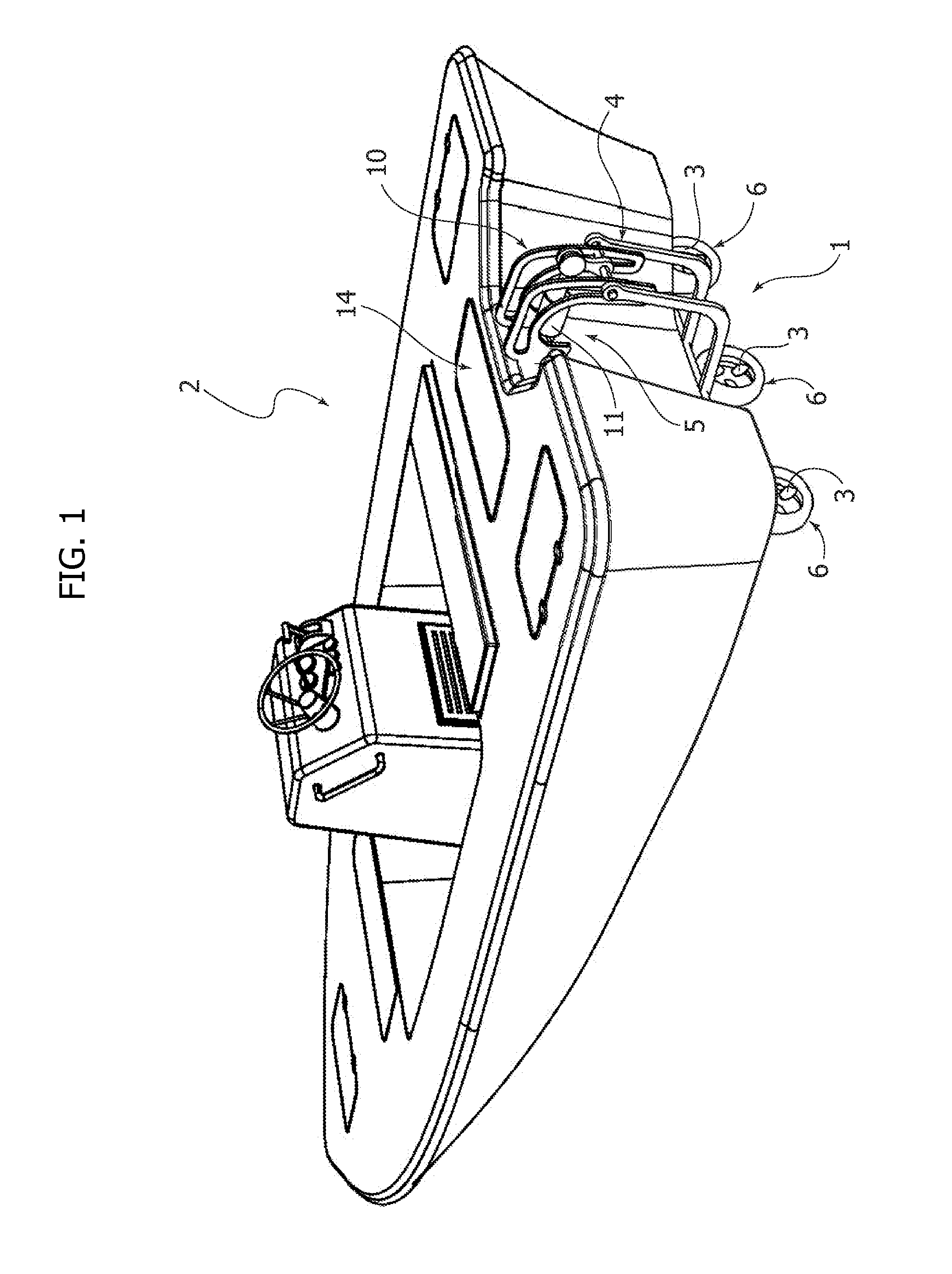
[0029]In FIG. 1, numeral 1 generally designates an outboard propulsion system for a vessel 2. It must be noted that the specific type of vessel shown in the drawings is given here purely by way of non-limiting example, while it is clearly apparent from the following description that the propulsion system according to the invention is applicable to an unlimited number of different types of vessel, as well as also to submarine vessels.

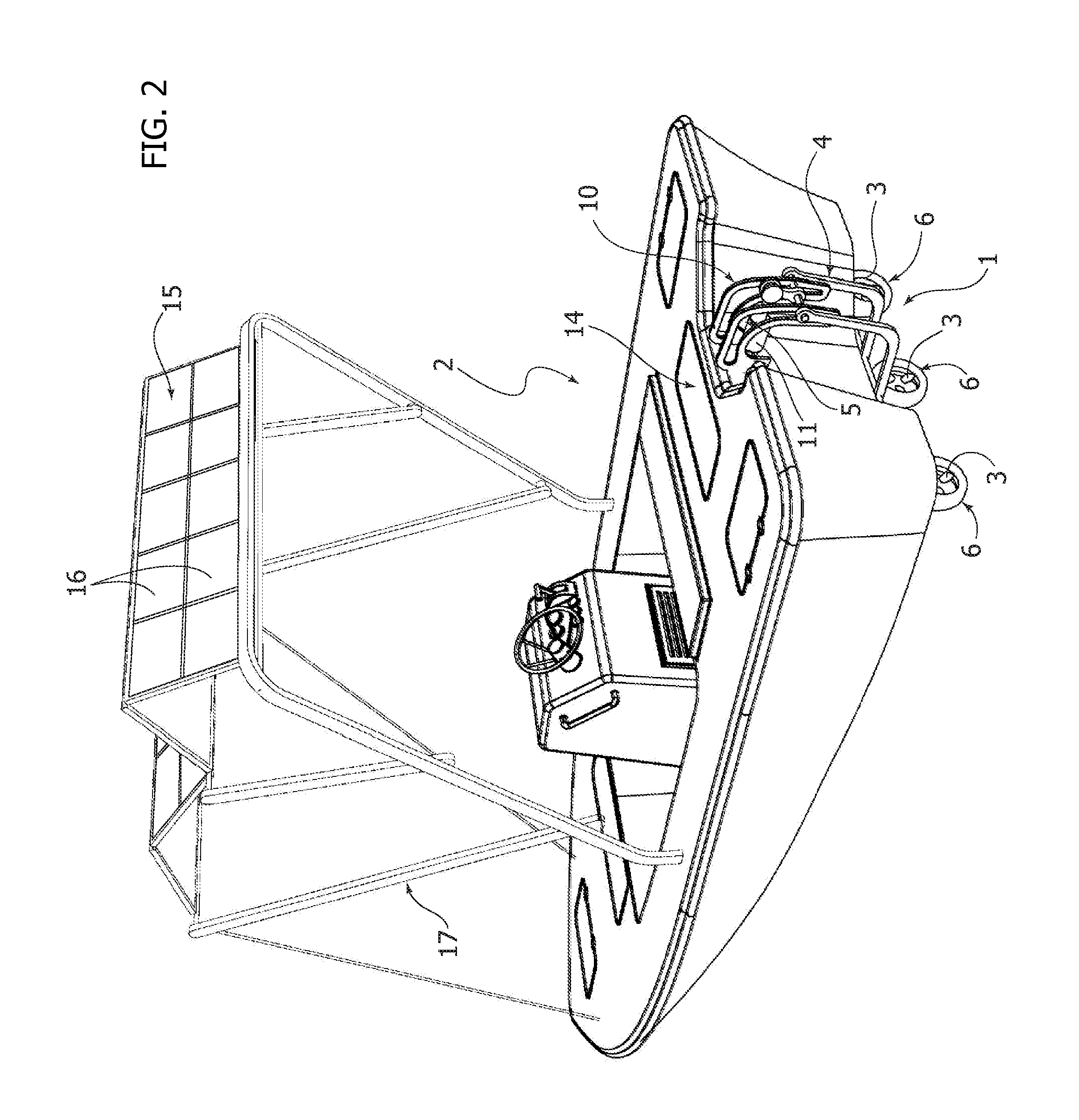
[0030]With reference also to FIGS. 2, 3, the propulsion 1 comprises a plurality of propellers 3 (in the specific case which is illustrated herein there are provided three propellers) carried by a supporting frame 4 provided with anchoring means of any known type, for anchoring to the transom wall 5 of the vessel 2.

[0031]According to an essential feature of the invention, each propeller 3 is associated to an electric motor 6 with a toroid geometry having an annular rotor R (see in particular FIG. 4) rotatable inside an annular stator S and defining therew...


PUM


Abstract

An outboard propulsion system for vessels includes a supporting structure (4) to be anchored to the transom wall (5) of the vessel and a plurality of propellers (3) carried by the supporting structure (4). Each propeller (3) is associated to an electric motor (6) with a toroid geometry, having an annular rotor (R) rotatable within an annular stator (S) and defining therewithin a central aperture (A), with the blades (3A) of the propeller (3) which are carried by the rotor (R) and extend to the central aperture (A).

Description

FIELD OF THE INVENTION[0001]The present invention relates to the field of outboard propulsion systems for vessels, of the type comprising a supporting structure to be anchored to a transom wall of the vessel and at least one propeller carried by said supporting structure.PRIOR ART[0002]Document U.S. Pat. No. 3,914,629 A discloses an outboard propulsion system according to the preamble of claim 1. Marine propellers with an electric motor having a toroid configuration and radial blades which extend from the wall of the rotor into the central aperture of the rotor are known from US 2003 / 0186601 A1, EP 2 332 824 A1, EP 2 591 993 A1, EP 2 591 995 A1.OBJECT OF THE INVENTION[0003]The object of the invention is that of providing a system of this type which is characterized by high efficiency, lightness and reduced dimensions.SUMMARY OF THE INVENTION[0004]In view of achieving this object, the invention provides an outboard propulsion system for vessels comprising a supporting structure to be...

Claims


Application Information

Patent Timeline
Patent Type & Authority Applications(United States)
IPC IPC(8): B63H20/32B64C29/00B63H20/08
CPCB63H20/32B63H2020/005B64C29/0008B63H20/08B63H25/42B63B39/08B63H20/00B63H21/17B63H2001/165B63H2023/005B64C11/001B64C39/024B64U10/13B64U30/20B64U50/19B63H1/16B64C27/08B64C27/14B64C29/0016
Inventor PERLO, PIETROGUERRIERI, PIETRO
Owner INTERACTIVE FULLY ELECTRICAL VEHICLES SRL
Why Eureka
Try Eureka