
Microstructured high friction surface for high friction to fabric, yarn and fibers

a high friction surface and microstructure technology, applied in the direction of traffic signals, roads, transportation and packaging, etc., can solve the problems of affecting the smoothness of the seam, the operator wrestling with the fabric, and the end of the seam can be confused,

Inactive Publication Date: 2015-12-24
HOOWAKI
View PDF3 Cites 23 Cited by
  • Summary
  • Abstract
  • Description
  • Claims
  • Application Information

AI Technical Summary

Benefits of technology

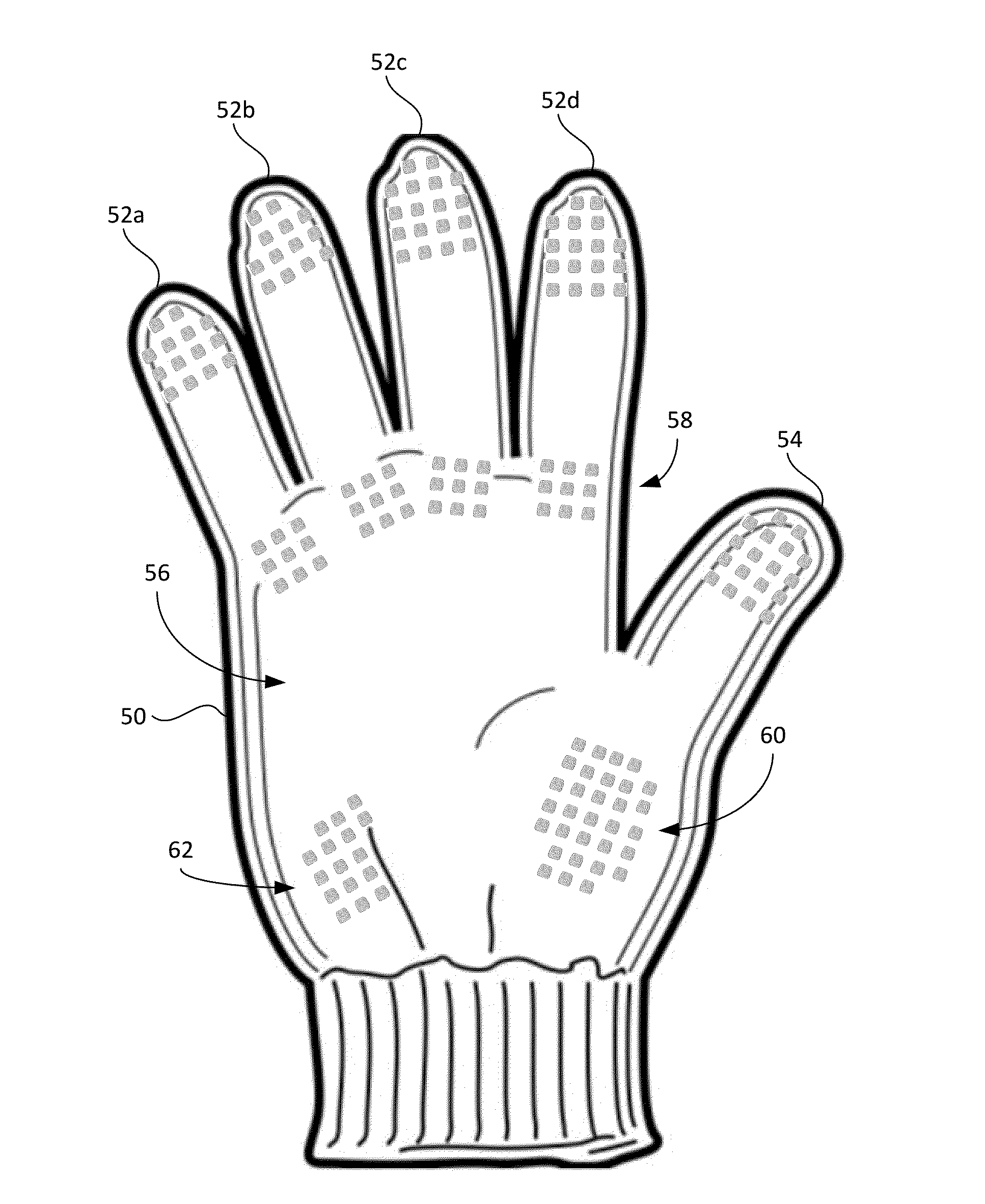
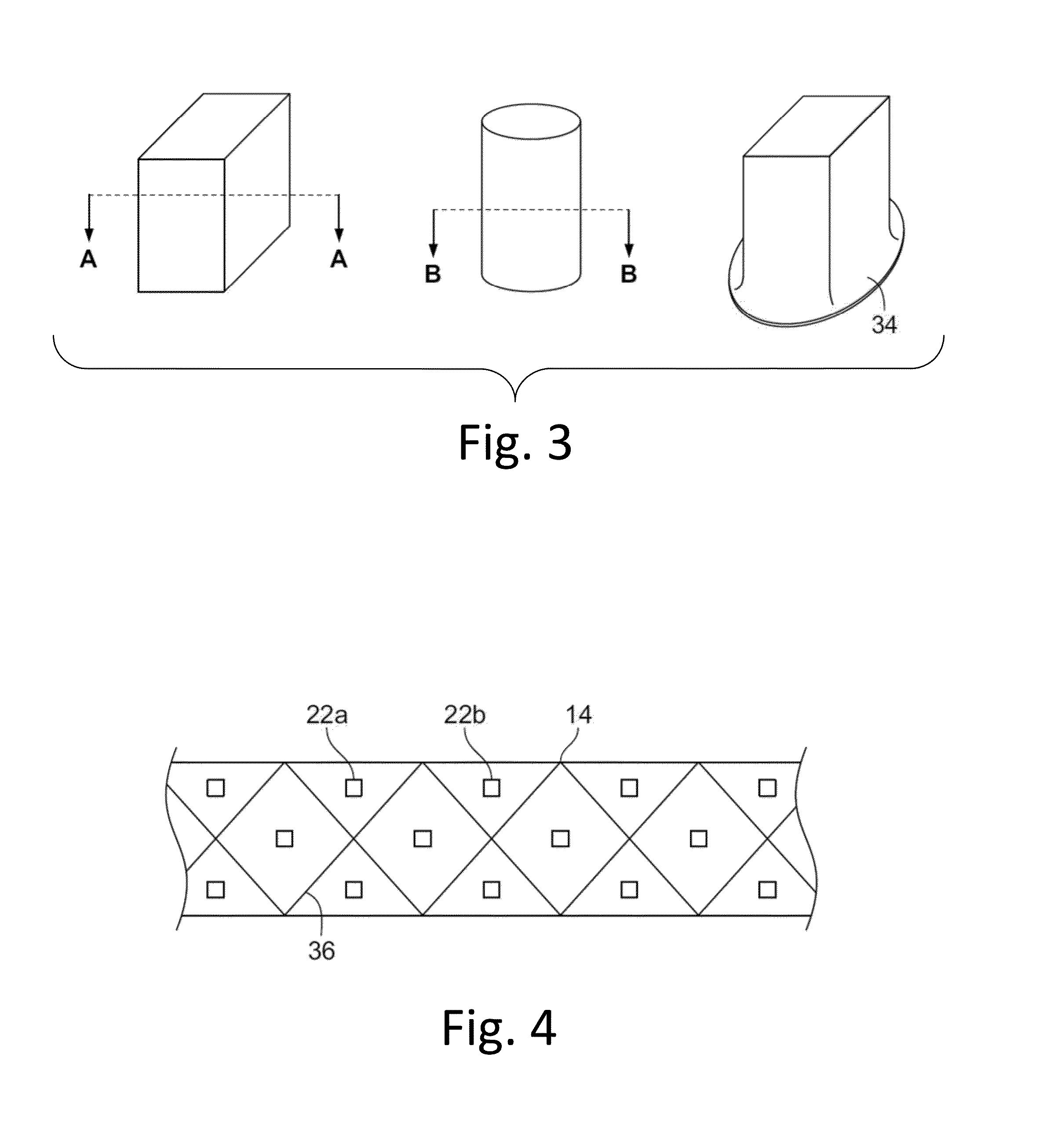
The patent describes a microstructured surface that can be applied to various surfaces such as gloves, machine surfaces, and sewing machine feed dogs. The surface has a unique arrangement of pillars that provide improved grip and reduced friction. The pillars have a specific shape, size, and spacing, and can be made from various materials such as metal or rubber. The surface is suitable for use in a variety of applications and can be manufactured using lithography, milling, or other methods. Overall, the patent describes a new technology for creating surfaces with improved grip and reduced friction.

Problems solved by technology

This problem is magnified with thin or slippery material.
Feed dogs that do not properly advance the fabric can cause the operator to wrestle with the fabric rather than have the sewing machine process pull the material through the presser foot with the proper tension.
Without the proper tension, a mismatch between the end of the seam can be created with more material leftover on one side than the other.
This can be a serious error resulting in undesirable seams when working with such material as nylon or silk and the like.
Another problem occurs when the sewing dogs do not advance the fabric, is that slippage occurs and the sewing dog can abrade and damage the fabric.
When the adjustment to the sewing machine is improperly made, the seam created is undesirable resulting in wasted material.
Furthermore, when the feeds dogs are worn, the material is not properly advanced which also creates an undesirable seam and waste.

Method used


Image

  • Microstructured high friction surface for high friction to fabric, yarn and fibers
  • Microstructured high friction surface for high friction to fabric, yarn and fibers
  • Microstructured high friction surface for high friction to fabric, yarn and fibers

Examples


Embodiment Construction

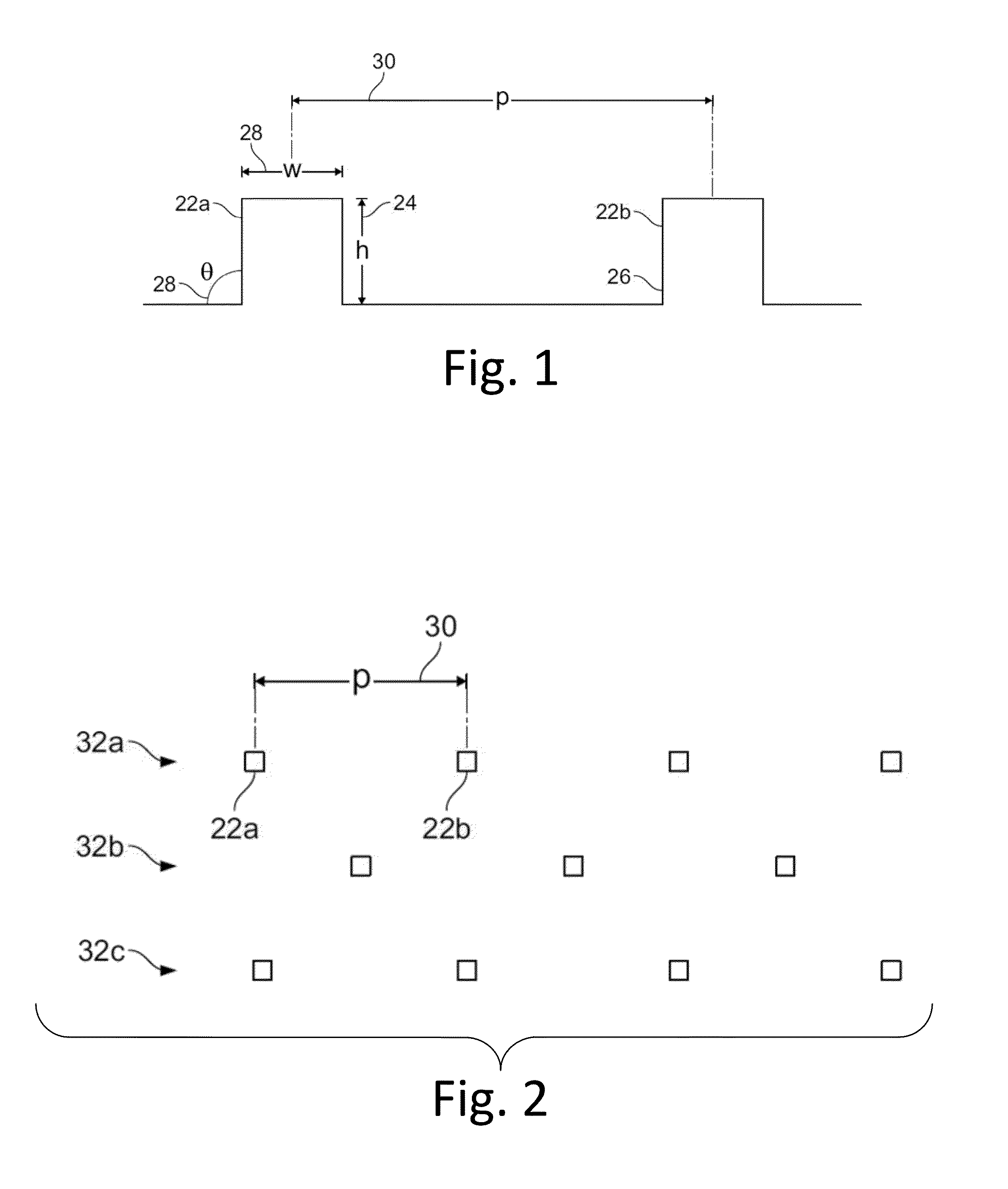
[0033]Referring to FIG. 1, one embodiment of the present invention is shown by an elevated view of the microstructures that can be attached or otherwise secured to a surface used for manipulating fabrics. The features of the microstructure can include pillars 22a and 22b. These pillars can have a height (h) shown as 24 that is between 50 μm and 1200 μm. In one embodiment, h is between 90 μm and 110 μm. In one embodiment, h is about 100 μm. If the height is too small, the microsurface has unacceptable low friction against fabric. If the pillar height is too large the microstructures become subject to bending and wear life is reduced. In one embodiment, h is greater than 70 μm.

[0034]In one embodiment, the pillars can include a coating. The coating can be a lubricating coating. The lubricating coating can be silicone oils, petroleum or mineral oils, PVD-PTFE coating, diamond like carbon coatings, nitride, or carbide coatings.

[0035]Each pillar can include a width (w) shown as 28 that is...


PUM


Abstract

This invention is directed to an improved contact surface for manipulating fabrics wherein the microstructure included on the contact surface having a plurality of pillars spaced apart in the range of 200 μm and 600 μm, having a height in the range of 50 μm and 1200 μm, a width of in the range of 70 μm and 300 μm, a wall draft angle between 0° and 15°, a density of in the range of 5,000 to 20,000 pillars per square inch, and a friction rating greater than 7. The contact surface can be included on a sewing machine feed dog, a glove, sporting equipment, firearm grip, hand rail, tools, and a strap such as for a satchel or backpack.

Description

FIELD OF THE INVENTION[0001]This invention is directed to an improved surface for use on articles such as sewing feed goods, walking dogs, gloves and other items that can benefit from improving fabric handling and management.BACKGROUND[0002]The clothing, textile and fabric industry have a very early origin. In the manufacturing of materials and products, the manipulation of the fabric is a constant need. The use of sewing needles also has early origins and is a common tool in the manufacturing of clothing and the like from fabrics. The industrial revolution resulted in the mechanization of manufacturing with inventions such as the waterwheel, steam-engine, sewing machines assembly lines and the like.[0003]The loom allows for complex patterns to be obtained. One example is the draw loom which allows a weaving pattern using treadles, or other mechanisms, where the needles are raised and lowered to open the shed in the warp threads. Runners were lifted in turn during the operation of t...

Claims


Application Information

Patent Timeline
IPC IPC(8): D05B91/06D05B27/02
CPCD05B91/06D05B27/02Y10T428/24388Y10T428/2438Y10T428/24372
Inventor HULSEMAN, RALPH A.HULSEMAN, SARAH
Owner HOOWAKI
Learn More