Apparatus and method for estimating power storage device degradation

a power storage device and applicator technology, applied in secondary cell servicing/maintenance, instruments, electrochemical generators, etc., can solve the problem of difficult direct measurement of the state of charge and achieve the effect of improving the accuracy of estimating the electric energy of the power storage devi

Active Publication Date: 2015-12-24
MITSUBISHI ELECTRIC CORP
View PDF2 Cites 8 Cited by
  • Summary
  • Abstract
  • Description
  • Claims
  • Application Information

AI Technical Summary

Benefits of technology

[0016]According to the present disclosure, it becomes possible to improve

Problems solved by technology

Directly measuring the state of charge

Method used


Image

  • Apparatus and method for estimating power storage device degradation
  • Apparatus and method for estimating power storage device degradation
  • Apparatus and method for estimating power storage device degradation

Examples


embodiment 1

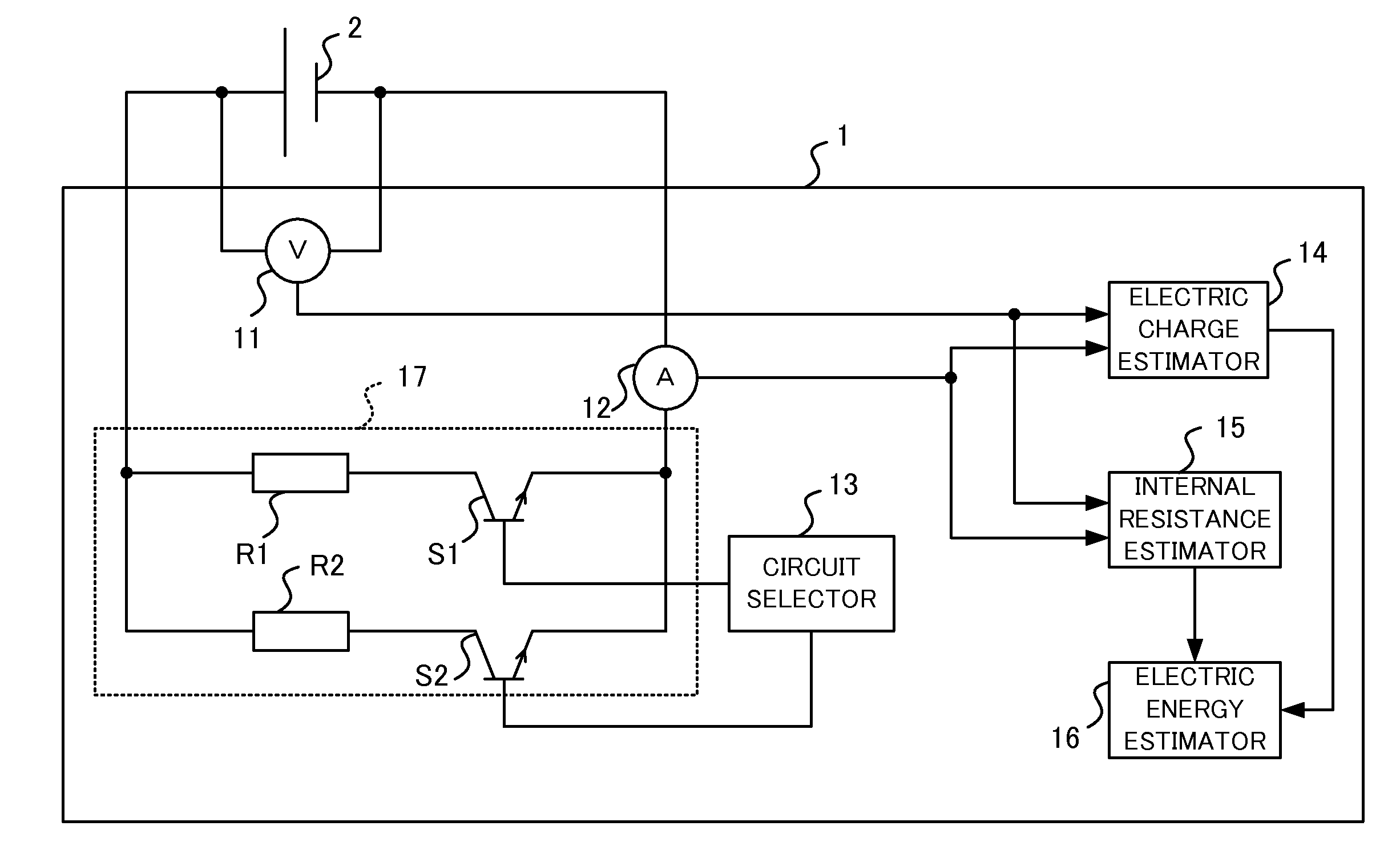
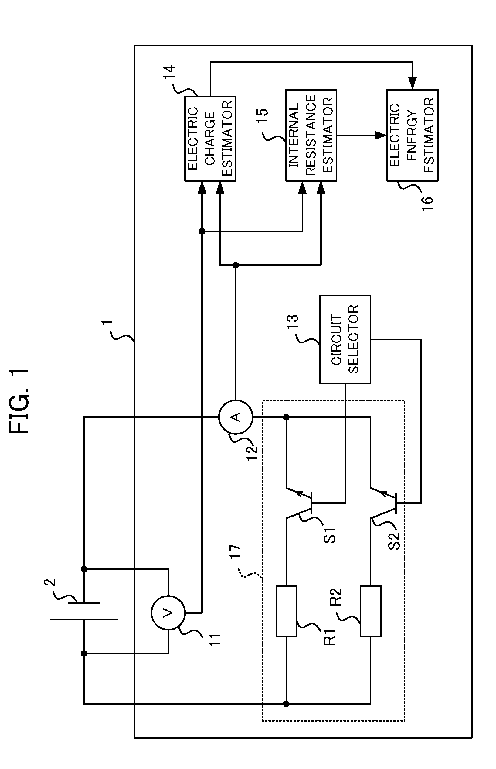
[0033]FIG. 1 is a block diagram illustrating an example configuration of an apparatus for estimating power storage device degradation according to Embodiment 1 of the present disclosure. The apparatus for estimating power storage device degradation 1 is provided with a voltage detector 11, a current detector 12, a circuit selector 13, an electric charge estimator 14, an internal resistance estimator 15, an electric energy estimator 16, resistors R1 and R2, and switches S1 and S2. The power storage device 2 is a secondary battery, for example, a nickel-metal hydride battery or a lithium-ion battery. As the power storage device 2 is repeatedly charged and discharged, the capacity of the power storage device 2 decreases due to degradation caused by the repeated charging and discharging, and the amount of storable electric energy decreases. The apparatus for estimating power storage device degradation 1 estimates degradation in the power storage device 2, or in other words, estimates th...

embodiment 2

[0058]FIG. 11 is a block diagram illustrating an example configuration of the apparatus for estimating power storage device degradation according to Embodiment 2 of the present disclosure. The apparatus for estimating power storage device degradation 1 according to Embodiment 2 is additionally provided with a temperature detector 18, in addition to the configuration of the apparatus for estimating power storage device degradation 1 according to Embodiment 1. Operations of the apparatus for estimating power storage device degradation 1 that differ from Embodiment 1 will be described.

[0059]The temperature detector 18 detects the surface temperature of the power storage device 2, or estimates the internal temperature of the power storage device 2, at arbitrarily determined times. The temperature detector or temperature estimation uses arbitrary technology of the related art. The temperature detector 18 detects the surface temperature of the power storage device 2 at times in conjunctio...


PUM


Abstract

Switches change the resistance value of a charge/discharge circuit in a period from starting a discharging at an upper limit voltage until the voltage reaches a lower limit voltage. An electric charge estimator computes electric charge by time-integrating current from a start of the discharging to an arbitrarily determined time, and computes a relationship between electric charge and voltage of a power storage device. An internal resistance estimator computes internal resistance based on voltages and currents of the storage device at times when resistance values are different. An electric energy estimator computes a relationship between electric charge and open voltage based on electric charge, voltage, current and internal resistance of the storage device. During charging or discharging of the storage device, the electric energy estimator estimates the electric energy of the power storage device based on the electric charge, the open voltage, the internal resistance, and the charge/discharge current.

Description

TECHNICAL FIELD[0001]The present disclosure relates to an apparatus and a method for estimating power storage device degradation, which estimates the electric energy of a power storage device.BACKGROUND ART[0002]To control the charging and discharging of a power storage device, it is necessary to accurately assess the dischargeable power and the chargeable power. In other words, it is necessary to accurately assess the open voltage (open-circuit voltage), the internal resistance, and the state of charge (SOC).[0003]Directly measuring the state of charge of a power storage device is difficult. However, a degree of correlation between the SOC and the open voltage of a power storage device has been recognized. Accordingly, with the method of computing the SOC of a secondary battery for an electric vehicle disclosed in Patent Literature 1, the battery internal resistance of a secondary battery is computed by multiplying a predetermined resistance value, a first resistance ratio based on...

Claims


Application Information

Patent Timeline
IPC IPC(8): G01R31/36
CPCG01R31/3624G01R31/3662G01R31/3648H01M10/44H01M10/48G01R31/392G01R31/3842G01R31/389
Inventor OKADA, YURUKISHIRAGA, SHOWADA, TOSHIHIROYOSHIOKA, SHOJI
Owner MITSUBISHI ELECTRIC CORP
Why Eureka
Try Eureka