Beam splitting system for laser ranging

a beam splitting and laser rangefinder technology, applied in distance measurement, surveying and navigation, instruments, etc., can solve the problems of large size, difficult installation and debugging, complicated structure of optical beam splitters of laser rangefinders, etc., to reduce the size of optical beam splitters, reduce the influence of transparent objects, and high stability and reliability

Active Publication Date: 2015-12-24
LANHAI PHOTOELECTRICITY TECH CO LTD
View PDF2 Cites 8 Cited by
  • Summary
  • Abstract
  • Description
  • Claims
  • Application Information

AI Technical Summary

Benefits of technology

[0003]To overcome the deficiencies of the optical beam splitter of an existing laser rangefinder, such as complicated structure, large size, high difficulty in installation and debugging and low stability, the present invention provides a beam splitting system for laser ranging, with simple and compact structure, small size, easy installation and debugging, good stability and high measurement precision.

Problems solved by technology

At present, optical beam splitters of laser rangefinders are complicated in structure, large in size, difficult in installation and debugging, difficult in controlling a beam splitting and propagation path, and low in stability.

Method used


Image

  • Beam splitting system for laser ranging
  • Beam splitting system for laser ranging
  • Beam splitting system for laser ranging

Examples


embodiment 1

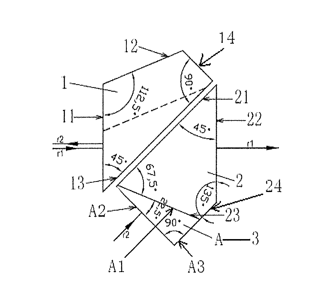
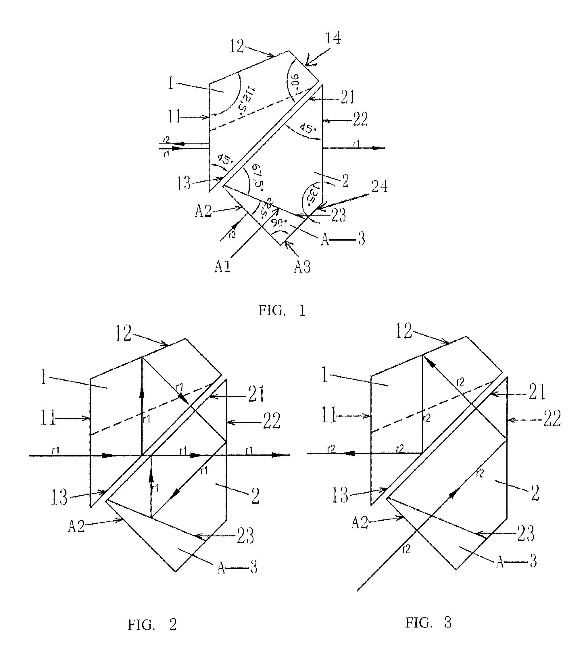
[0040] A beam splitting system for laser ranging is provided, referring to FIGS. 1, 2 and 3, including: a roof half-pentaprism (1), an isosceles prism (2) and a compensating prism (3), where the compensating prism is a compensating prism I (A).

[0041]The roof half-pentaprism includes a roof transceiving surface (11), an outer roof reflecting surface (12), an inner roof reflecting surface (13) and a top roof surface (14). Two ends of the roof transceiving surface are intersected with one end of the outer roof reflecting surface and one end of the inner roof reflecting surface, respectively. Two ends of the top roof surface are intersected with the other end of the outer roof reflecting surface and the other end of the inner roof reflecting surface, respectively. An included angle between the outer roof reflecting surface and the roof transceiving surface is 112.5°. An included angle between the roof transceiving surface and the inner roof reflecting surface is 45°. An included angle b...

embodiment 3

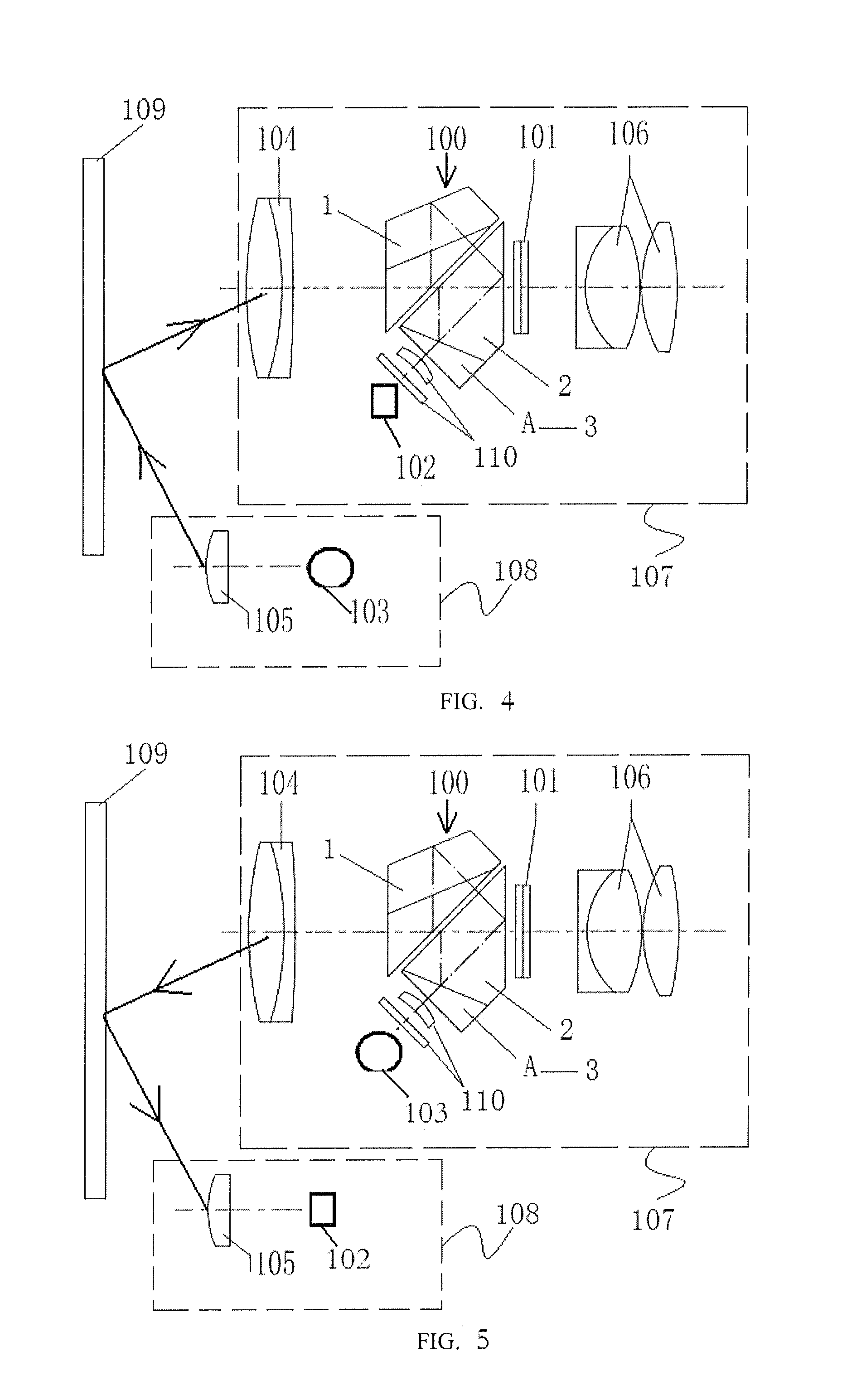
[0050] Referring to FIG. 10, the difference between FIG. 10 and FIG. 4 lies in that: first, the optical beam splitter (100) in the transceiving system I (107) in FIG. 4 is replaced with an optical beam splitter (200), the compensating prism (3) of the optical beam splitter (200) is a compensating prism II (B), and the compensating prism II includes a first compensation transceiving surface II (B3) and a second compensation transceiving surface II (B4); second, the combined lens (110) and the receiver (102) are disposed on one side opposite to the first compensation transceiving surface II of the compensating prism II (B), and the combined lens (110) is disposed between the first compensation transceiving surface II (B3) and the receiver (102); and third, a group of combined reflecting lens (111) are disposed on one side opposite to the second compensation transceiving surface II of the compensating prism II (B), and the LCD (101) is disposed in front of the reflecting surfaces of th...

embodiment 5

[0054] Referring to FIG. 16, the difference between FIG. 16 and FIG. 10 lies in that: first, the optical beam splitter (200) in the transceiving system I (107) in FIG. 10 is replaced with an optical beam splitter (300), the compensating prism (3) of the optical beam splitter (300) is a compensating prism III (C), and the compensating prism III includes a first compensation transceiving surface III (C2) and a second compensation transceiving surface III (C3); second, the combined lens (110) and the receiver (102) are disposed on one side opposite to the second compensation transceiving surface III (C3) of the compensating prism III (C), and the combined lens (110) is disposed between the second compensation transceiving surface III (C3) and the receiver (102); and third, a group of combined reflecting lens (111) are disposed on one side opposite to the first compensation transceiving surface III of the compensating prism III (C), and the LCD (101) is disposed in front of the reflecti...


PUM


Abstract

A beam splitting system for laser ranging includes a roof half-pentaprism, an isosceles prism and a compensating prism. Due to different compensating prisms, there are four light splitting combinations in total. Light of a certain wavelength is incident from one side of the roof half-pentaprism, and is reflected therein for several times and finally emergent into the isosceles prism where it is reflected for several times and finally emergent in a direction consistent with an incident light axis. Light of another wavelength is incident from one side of the compensating prism, and finally emergent from one side of the roof half-pentaprism or one side of the isosceles prism. Different light splitting ways may be caused due to different positions of both prisms and data LCDs. A number of different optical ranging systems will be provided if a laser rangefinder employs different light splitting combinations.

Description

TECHNICAL FIELD[0001]The present invention relates to the technical field of beam splitting, and particularly to a beam splitting system for laser ranging.BACKGROUND OF THE INVENTION[0002]At present, optical beam splitters of laser rangefinders are complicated in structure, large in size, difficult in installation and debugging, difficult in controlling a beam splitting and propagation path, and low in stability.SUMMARY OF THE INVENTION[0003]To overcome the deficiencies of the optical beam splitter of an existing laser rangefinder, such as complicated structure, large size, high difficulty in installation and debugging and low stability, the present invention provides a beam splitting system for laser ranging, with simple and compact structure, small size, easy installation and debugging, good stability and high measurement precision.[0004]To achieve the above object, the present invention employs the following technical solutions.[0005]A beam splitting system for laser ranging is p...

Claims


Application Information

Patent Timeline
Patent Type & Authority Applications(United States)
IPC IPC(8): G02B27/14G01C3/02G02B5/04
CPCG02B27/145G01C3/02G02B5/04G02B27/126
Inventor ZUO, LUOQIAN, XIANGWEI
Owner LANHAI PHOTOELECTRICITY TECH CO LTD
Why Eureka
Try Eureka